Self Tuning RFID

a self-tuning, radio frequency identification technology, applied in the direction of memory record carrier reading problems, instruments, computing, etc., can solve the problems of difficult insertion of antennas into rfid tags, difficult antenna compensation, and inability to have good low vswr characteristics across the intended band of operation, so as to avoid obscuring the purpose

Active Publication Date: 2010-01-28
SYMBOL TECH LLC
View PDF21 Cites 42 Cited by
  • Summary
  • Abstract
  • Description
  • Claims
  • Application Information

AI Technical Summary

Benefits of technology

[0008]This summary is for the purpose of summarizing some aspects of the inventions described more fully in other sections of this patent document. It briefly introduces some preferred embodiments. Simplifications or omissions may be made to avoid obscuring the purpose of the section. Such simplifications or omissions are not intended to limit the scope of the claimed inventions. The inventions can be implemented in numerous ways, including methods, systems, devices, and computer readable medium. Several embodiments of the inventions are discussed below, but they are not the only ways to practice the inventions described herein.
[0009]The invention provides an RFID tag arrangement that is self tuning. The RFID tag is powered by a charge pump having multiple stages, each having a tap so that the number of stages used can be selected. The antenna of the RFID tag is connected to transmitter and receiver circuits through a switchable impedance matching circuit. A tuning circuit includes first and second digital control loops. The first digital control loop causes the RFID tag to cycle through successive taps of the charge pump circuit until a maximum voltage tap has been reached. The maximum voltage occurs when the charge pump resistance matches the real component of antenna impedance. By finding the right tap on the charge pump, the real component of antenna impedance is matched. A second digital control loop controls connection of components of the impedance matching circuit coupled to the antenna. Means are provided for updating the second digital control loop by the first digital control loop.

Problems solved by technology

Integrating an antenna into a RFID tag is difficult at best.
Design compromises necessary for available space result in antenna arrangements that are sub-optimal.
They do not have a good low VSWR characteristic across their intended band of operation.
Such antenna compensation becomes more difficult when there is little space to work with.
The problem of antenna compensation becomes even more difficult in an RFID tag environment.

Method used


Image

  • Self Tuning RFID
  • Self Tuning RFID
  • Self Tuning RFID

Examples


Embodiment Construction

Exemplary Operating Environment

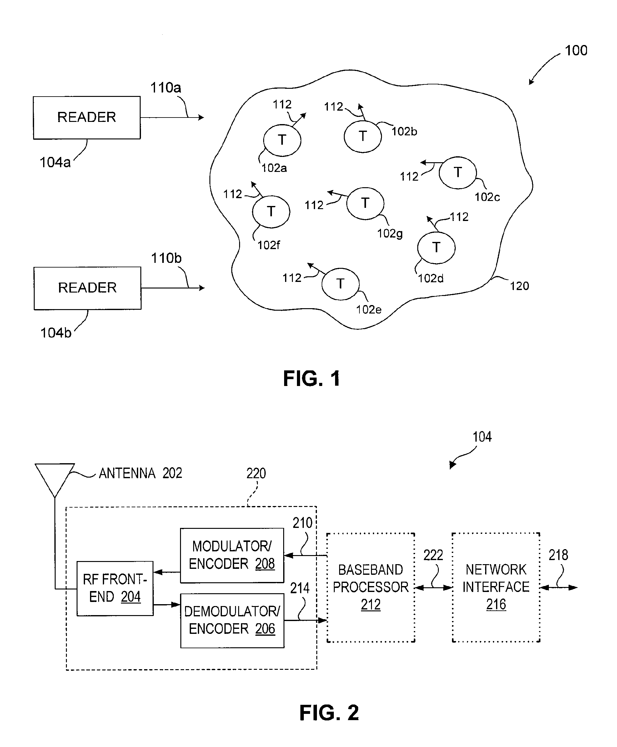
[0021]Before describing embodiments of the inventions in detail, it may be helpful to understand an example RFID communications environment in which the inventions may be implemented. FIG. 1 illustrates an environment 100 where RFID tag readers 104 (readers 104a and 104b shown in FIG. 1) communicate with an exemplary population 120 of RFID tags 102. As shown in FIG. 1, the population 120 of tags includes seven tags 102a-102g. A population 120 may include any number of tags 102.

[0022]Environment 100 includes any number of one or more readers 104. For example, environment 100 includes a first reader 104a and a second reader 104b. Readers 104a and / or 104b may be requested by an external application to address the population of tags 120. Alternatively, reader 104a and / or reader 104b may have internal logic that initiates communication, or may have a trigger mechanism that an operator of a reader 104 uses to initiate communication. Readers 104a and 104b may...


PUM


Abstract

The antenna of an RFID tag is automatically tuned by controlling both the real and imaginary components impedance “seen” by the antenna. The real component (resistive) is controlled by controlling a tap of a charge pump circuit of the tag. The imaginary (reactive) component is controlled by connecting one or more reactive elements of an antenna tuning circuit to the antenna. The real component is controlled by a first digital control loop that automatically activates successive taps on a charge pump of the RFID tag which effectively controls the resistance seen by the antenna. A second digital control loop controls the connection of the various reactive components.

Description

BACKGROUND[0001]1. Field of Invention[0002]The invention relates in general to the use of radio frequency identification (RFID) tags and RFID tag readers (also known as “interrogators”). In particular, the invention relates to the configuration and operation of RFID tags that can self tune an integrated antenna so as to automatically adjust to a resonant frequency.[0003]2. Related Art[0004]Radio frequency identification (RFID) tags are electronic devices that may be affixed to items whose presence is to be detected and / or monitored. RFID tags are classified based on standards defined by national and international standards bodies (e.g., EPCGlobal and ISO). Standard tag classes include Class 0, Class 1, and Class 1 Generation 2 (referred to herein as “Gen 2”). The presence of an RFID tag, and therefore the presence of the item to which the tag is affixed, may be checked and monitored wirelessly by an “RFID reader”, also known as a “reader-interrogator”, “interrogator”, or simply “rea...

Claims


Application Information

Patent Timeline
Patent Type & Authority Applications(United States)
IPC IPC(8): G08B13/14
CPCG06K7/0008G06K19/07749G06K19/0713
Inventor SHANKS, WAYNE E.
Owner SYMBOL TECH LLC
Why Eureka
Try Eureka