Image forming apparatus

Active Publication Date: 2010-01-28
CANON KK
View PDF12 Cites 33 Cited by
  • Summary
  • Abstract
  • Description
  • Claims
  • Application Information

AI Technical Summary

Benefits of technology

[0019]For example, the present invention can control option apparatuses to smoothly convey a reco

Problems solved by technology

These problems are negligible at low conveyance speeds of image forming apparatuses,

Method used


Image

  • Image forming apparatus
  • Image forming apparatus
  • Image forming apparatus

Examples


Embodiment Construction

[0059]Preferred exemplary embodiments of the present invention will be described in detail below with reference to the accompanying drawings. Constituent elements described in the embodiments are merely examples, and the scope of the invention is not limited to them.

[0060]A first exemplary embodiment will be described as follows.

[0061]

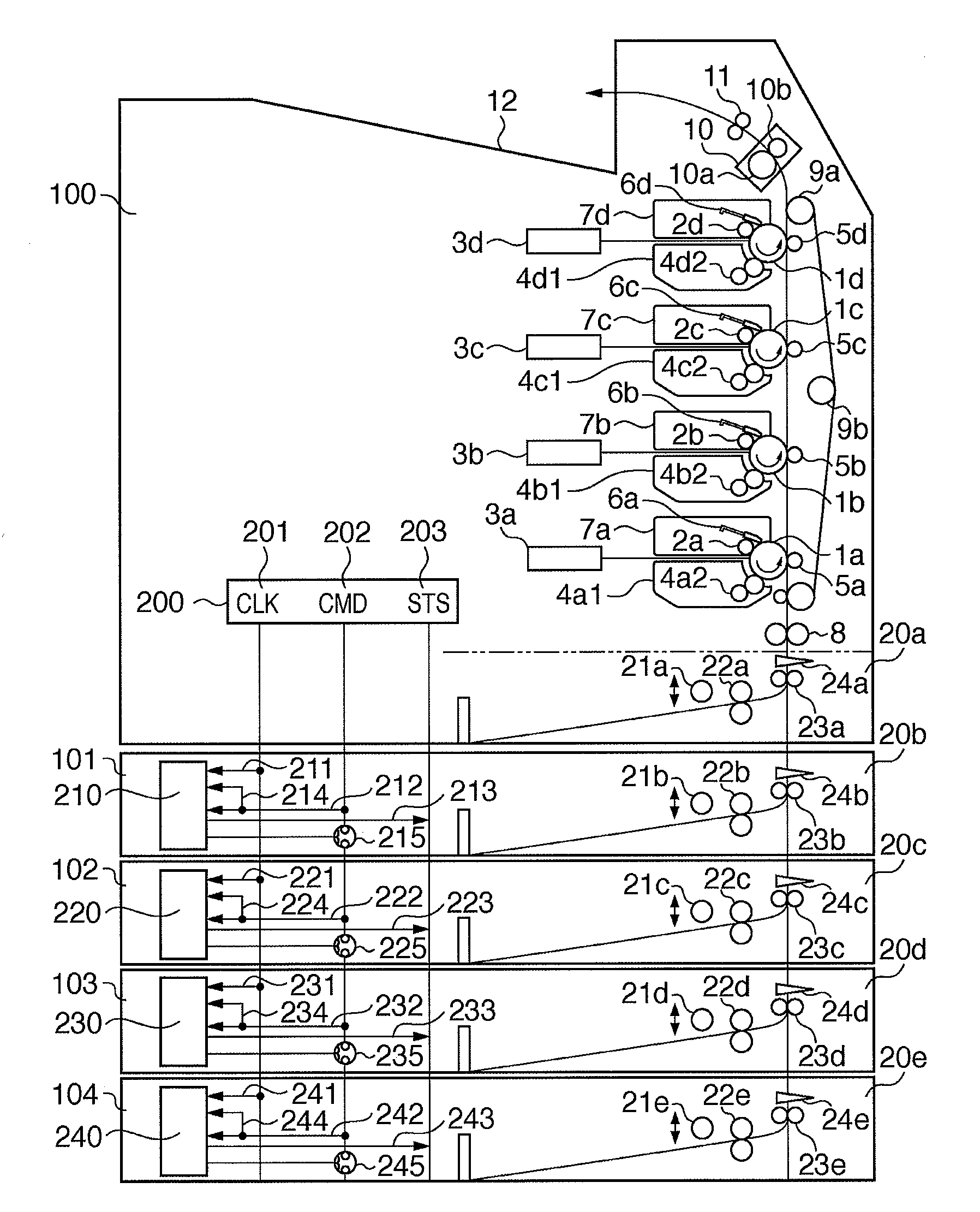
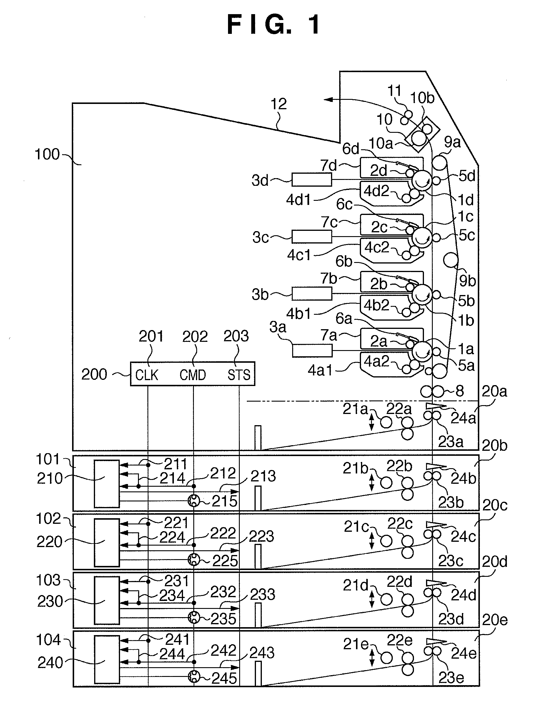
[0062]FIG. 1 is a sectional view showing the arrangement of an image forming apparatus capable of connecting three or more option apparatuses according to the first exemplary embodiment. In FIG. 1, four option sheet feeding apparatuses 101, 102, 103, and 104 are attached to an image forming apparatus main body 100.

[0063]The whole arrangement will be explained first. The image forming apparatus main body 100 includes four photosensitive members 1, that is, 1a to 1d each serving as an image carrier. Charging units 2, that is, 2a to 2d each for uniformly charging the surface of the photosensitive member, and exposure units 3, that is, 3a to 3d each for em...


PUM


Abstract

This invention provides an image forming apparatus capable of smoothly controlling option apparatuses while suppressing power consumed by conveyance, compared to a conventional technique. To achieve this, the control unit of the image forming apparatus issues a control instruction by serial communication via a common communication line to drive not all but two or more option apparatuses at once.

Description

BACKGROUND OF THE INVENTION[0001]1. Field of the Invention[0002]The present invention relates to a communication technique between an image forming apparatus main body and an option apparatus attached to it.[0003]2. Description of the Related Art[0004]Conventionally, a plurality of option apparatuses attachable to an image forming apparatus main body are connected to the image forming apparatus. While communicating with the option apparatuses, the image forming apparatus main body controls them to execute a cooperative operation for sheet feeding / conveyance or sheet delivery / conveyance.[0005]For example, according to Japanese Patent Laid-Open No. 09-193508 (patent reference 1), an image forming apparatus main body communicates with a plurality of option apparatuses to transmit / receive data by serial communication synchronized with common clocks.[0006]Signal lines for clocks and data are commonly connected to a plurality of option apparatuses. In addition, an individual signal line i...

Claims


Application Information

Patent Timeline
IPC IPC(8): G06F3/12
CPCG03G15/6508G03G15/5004
Inventor ITO, MITSUHIRO
Owner CANON KK
Why Eureka
Try Eureka