
Dental Retractor

Inactive Publication Date: 2010-01-28
BRAMAN BRAD
View PDF13 Cites 23 Cited by
  • Summary
  • Abstract
  • Description
  • Claims
  • Application Information

AI Technical Summary

Benefits of technology

[0011]An additional object of this invention is the provision of such a retractor which may be assembled from multiple components with ease to allow adjustment of the optics of the imaging mirror to the user's preference.
[0026]The device may be provided with one or all of the components of the reflective surface, illumination means, pivot, and means for suction of fluids from the mouth, depending on how much of an increase in utility is desired. However, each addition in combination with the reflective surface will in itself provide a great improvement on available dental retractors.

Problems solved by technology

Consequently, the surgeon, and frequently the assistant to the surgeon, manipulate a number of surgical instruments within the mouth of the patient concurrently, much to the chagrin of the patient.
This can have a fatiguing effect on the surgeon or assistant assigned the task of imparting that force and maintaining it using their fingers, hand and arm.
As noted, the field can become very crowded due to the inherent limit of space provided by the area of the mouth.

Method used


Image

  • Dental Retractor
  • Dental Retractor
  • Dental Retractor

Examples


Embodiment Construction

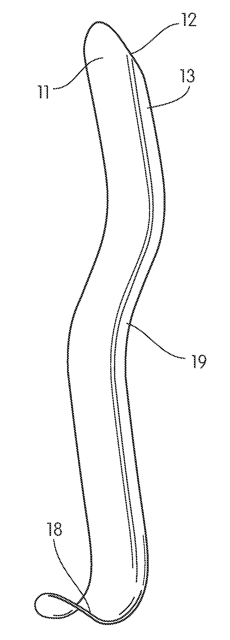
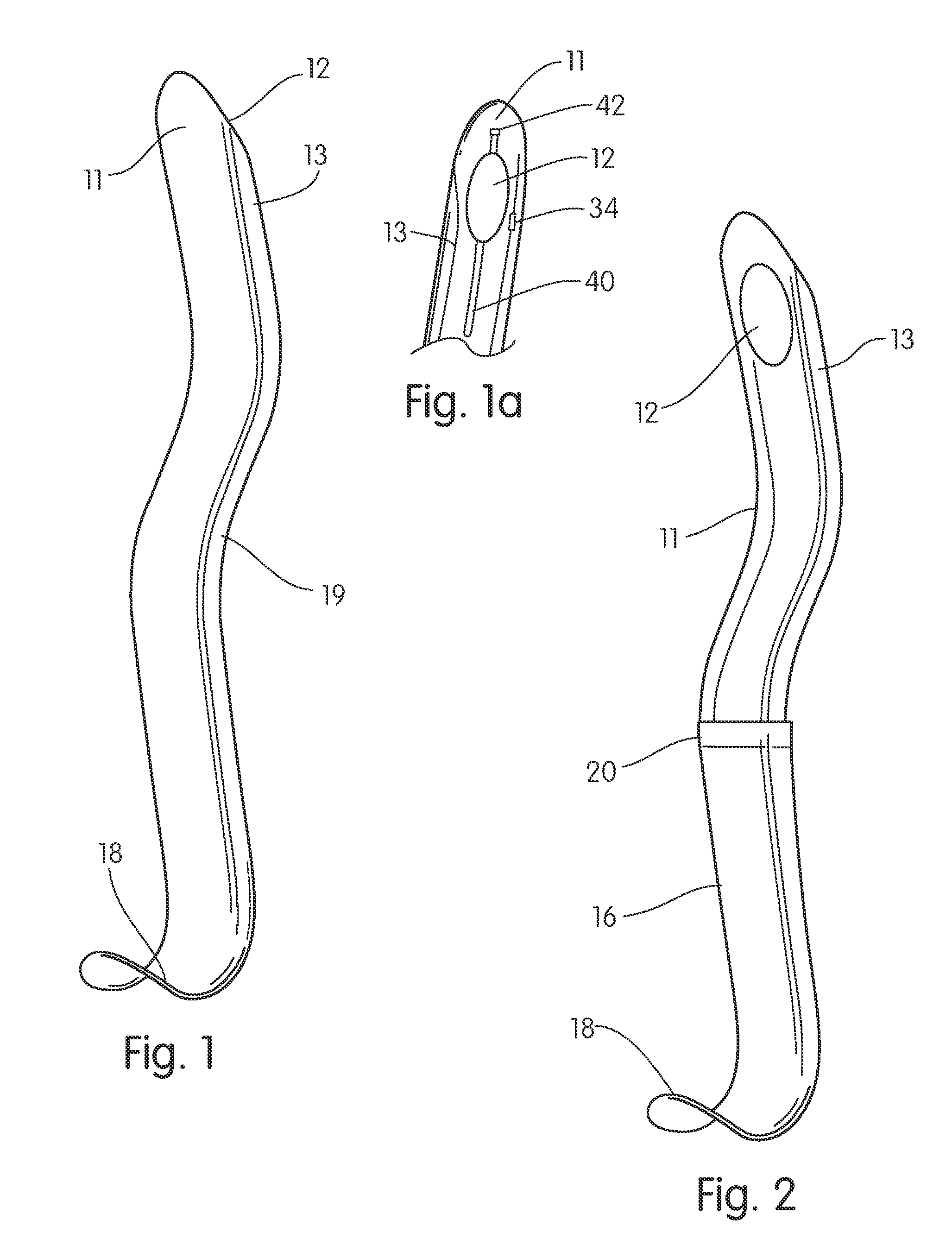
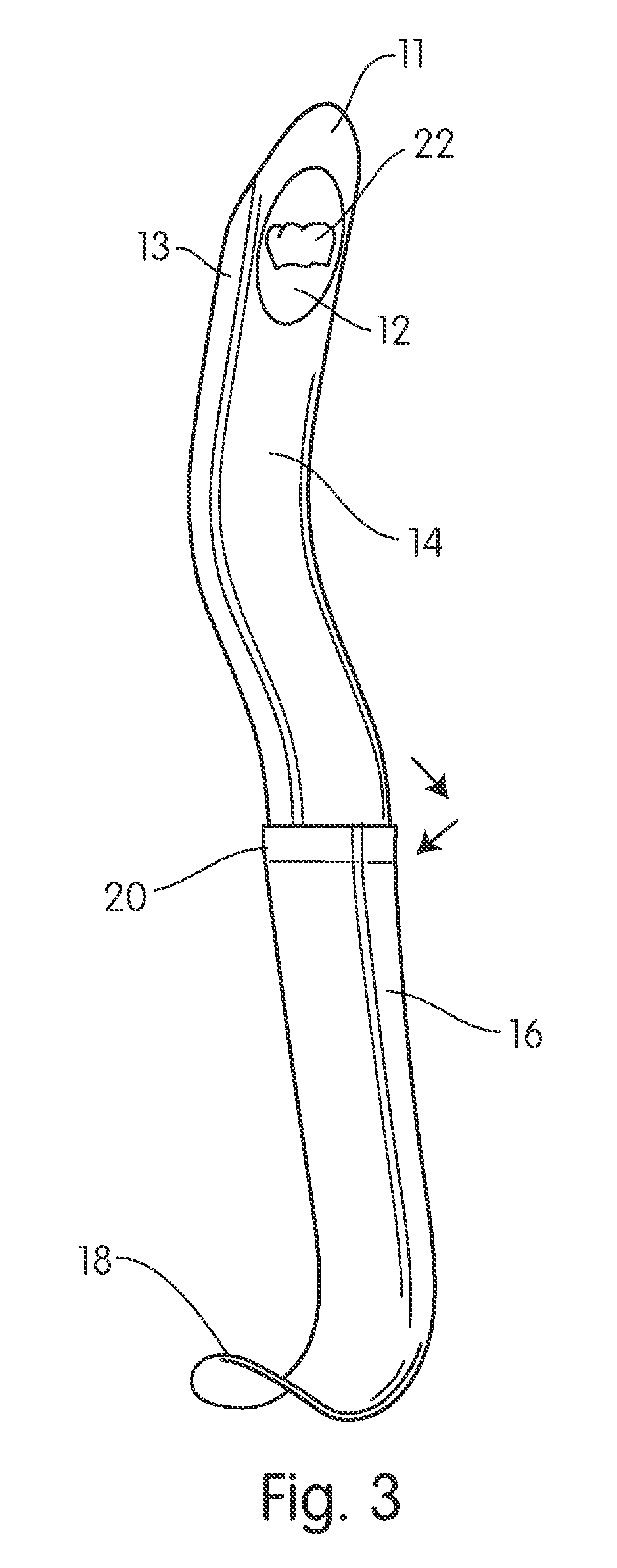
[0036]Referring now to the drawings in FIGS. 1-7, wherein similar parts are identified by like reference numerals, there is seen in FIG. 1 a perspective view of the device 10 as would be provided with a dental retractor 14 body. As shown in FIG. 1a, an engaged reflective surface 12 is positioned at a distal end 11 of the dental retractor 14 in between stiffening sidewalls 13. The distal end 11 is somewhat pointed to allow engagement between teeth or gums or other areas of the mouth and allow the user a point from which to apply force with the proximate end 16 to move the cheek and lips out of the way during a surgery.

[0037]At the proximate end 16 is formed a curved portion 18 adapted for the engagement of the fingers of the user during employment of the retractor 14 in a surgery. In a first preferred mode of the device, shown in FIGS. 1 and 1a, during a surgery the device 10 is placed in an as-used position by positioning the distal end 11 at the proper position in the mouth to retr...


PUM


Abstract

A dental retractor for employment during dental and oral surgery procedures. The device employs a reflective surface at a distal end which is conventionally used adjacent to the surgery site in the patient's mouth. The reflective surface eliminates the need for additional mirrors and such in the patient's mouth. Additionally provided is a proximal end that will adapted for ergonomic positioning in the hand of the user.

Description

[0001]This application claims the benefit of priority from U.S. Provisional Patent Application Ser. No. 61 / 083,073 filed Jul. 23, 2008, which is incorporated herein in its entirety by reference.FIELD OF THE INVENTION[0002]The disclosed device relates to instruments employed in dental surgery. More particularly, it relates to a dental retractor which includes a reflective surface at a distal end adjacent to the surgery site in the patient's mouth. Additionally, it includes means for adjusting the proximate end for ergonomic positioning for the user.BACKGROUND OF THE INVENTION[0003]Dental surgery, especially in the rear portions of the mouth, is conducted in the narrow confines of that mouth with dental instruments which must be employed with great precision by the medical professional using them. As a consequence, it has become conventional during such procedures to employ retractors to expand the area employable to manipulate instruments. Further, such retractors are also deployed d...

Claims


Application Information

Patent Timeline
IPC IPC(8): A61C3/00
CPCA61B1/00181A61B1/247A61B1/06A61C17/088A61C9/0033
Inventor BRAMAN, BRAD
Owner BRAMAN BRAD
Learn More