Magnet And Pin for Block Toy

a technology which is applied in the field of magnets and pins for block toys, can solve the problems of inconvenient removal of conventional art and undesired removal from blocks, and achieve the effects of convenient removal, enhanced productivity and easy replacemen

Inactive Publication Date: 2010-01-28
KIM DONG WAN
View PDF3 Cites 31 Cited by
  • Summary
  • Abstract
  • Description
  • Claims
  • Application Information

AI Technical Summary

Benefits of technology

[0012]A fastening pin (11) and a rotary magnet (14) for block toys according to the present invention can be firmly coupled to and easily removed from the block, unlike the conventional block toy, which uses a permanent magnet 20 and a holder 21. Therefore, there are advantages in that productivity is enhanced and the rotary magnet (14) can be easily replaced with a new one.
[0013]Furthermore, because the rotary magnet (14), which is fitted over the fastening pin (11), is rotated in a clockwise or counterclockwise direction in place, attractive force can be reliably generated between blocks (1). Thus, the blocks (1) can be easily connected to each other. Therefore, the present invention is advantageous in that the competitiveness of products can be increased compared to conventional block toys using permanent magnets.

Problems solved by technology

However, the conventional art is problematic in that the holders 21, which have been force-fitted into the block 1, may be undesirably removed from the block 1 after repeated use for a long period of time.
However, in the case where the permanent magnets 20 are attached to the sidewalls of the respective holders 21, even in the case where repulsive force is generated between the permanent magnets, because the permanent magnets cannot change their orientation and thus do not generate attractive force therebetween, the blocks 1 are not connected to each other.

Method used


Image

  • Magnet And Pin for Block Toy
  • Magnet And Pin for Block Toy
  • Magnet And Pin for Block Toy

Examples


Embodiment Construction

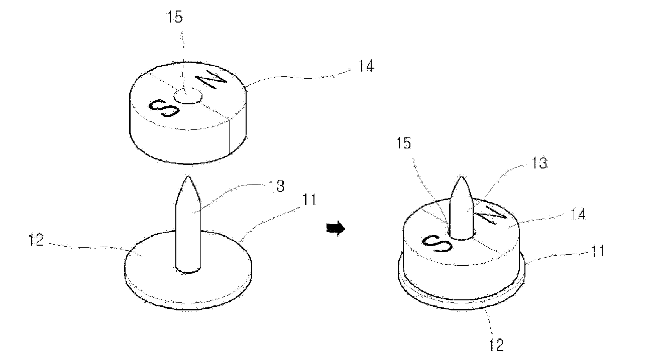
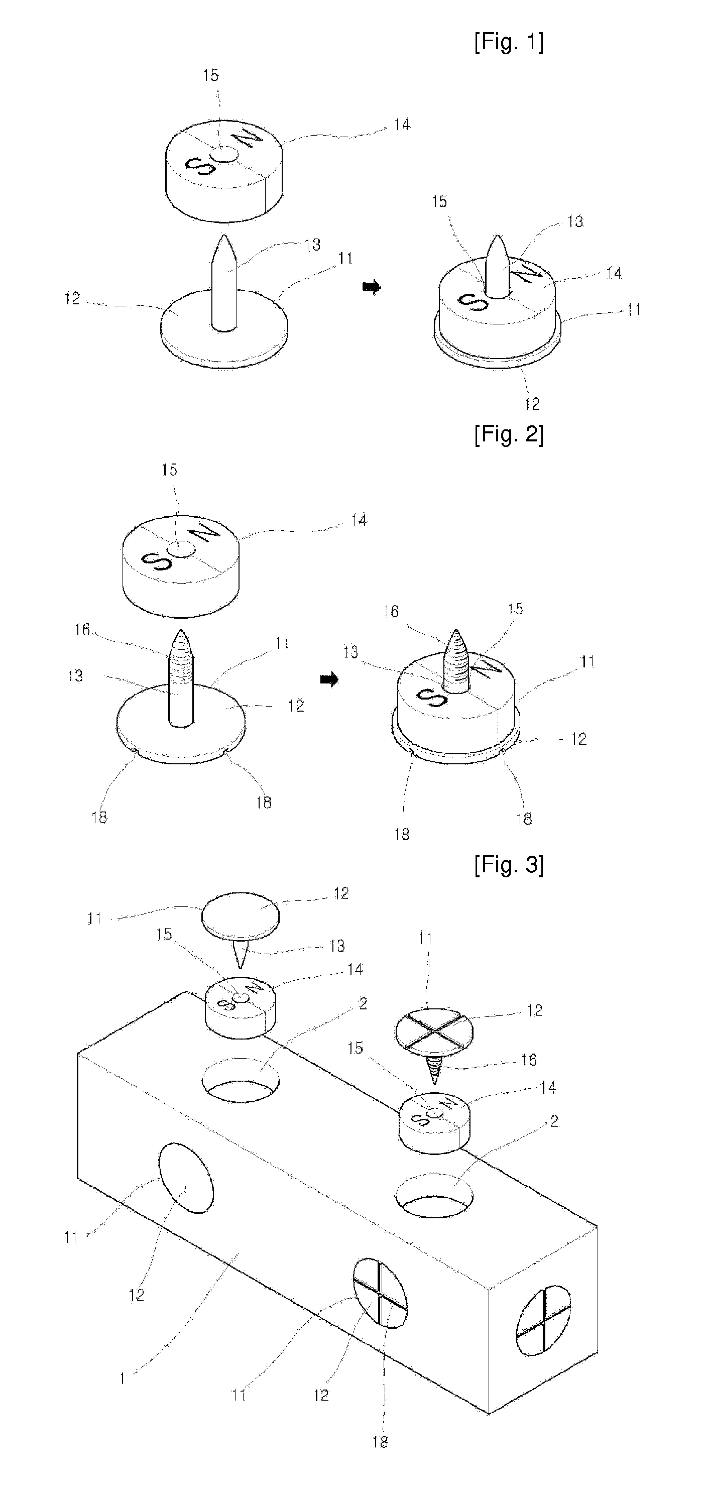
[0033]Hereinafter, embodiments of a rotary magnet and a fastening pin for block toys according to the present invention will be described in detail with reference to FIG. 1.

[0034]The fastening pin 11 includes a fastening plate part 12, which has a diameter suitable to firmly fit it into a corresponding seating depression 2 of a block 1, and a pin part 13, which has a height greater than that of the rotary magnet 14.

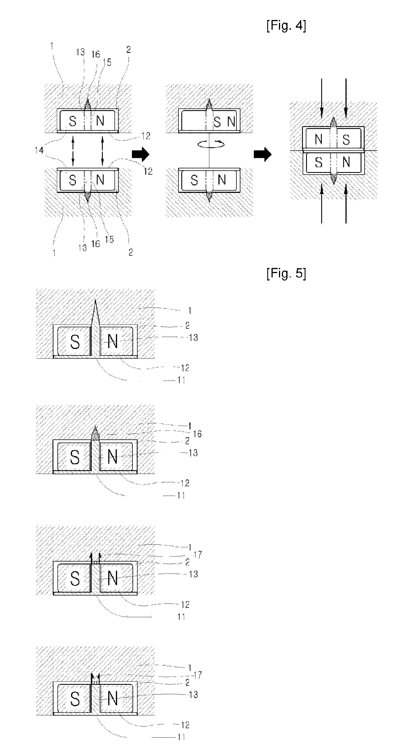
[0035]The rotary magnet 14 has an N pole and an S pole on the left and right parts thereof. A through hole 15, into which the pin part 13 is inserted, is formed through the center of the rotary magnet 14.

[0036]The fastening pin 11 has a shape similar to a thumbtack. Preferably, the diameter and thickness of the fastening plate part 12 are, respectively, approximately 6 mm and 0.3 mm, and the height of the pin part 13 is approximately 4 mm. Furthermore, the fastening pin 11 is preferably made of stainless steel (SUS304) or SECC steel, which is plated with innoxious materia...


PUM


Abstract

A rotary magnet and a fastening pin for block toys are disclosed. The object of the present invention is to provide a structure such that the production cost can be reduced, the magnet and the pin can be easily installed in a block, and appropriate attractive force can be easily generated between blocks. The fastening pin (11) include a fastening plate part (12), which has a diameter suitable for fitting the fastening plate part into a seating depression (2) of the block (1), and a pin part (13), which has a height greater than that of the rotary magnet (14). The rotary magnet (14) has an N pole and an S pole on the left and right parts thereof. A through hole (15) is formed through the center of the rotary magnet (14), so that the pin part (13) can be inserted into the through hole (15).

Description

TECHNICAL FIELD[0001]The present invention relates, in general, to rotary magnets and fastening pins for block toys, in which blocks are connected to each other using magnetic force to form structures having various shapes, and, more particularly, to a rotary magnet and a fastening pin for block toys for which the production cost is reduced, which can be easily installed in a block, and which can easily generate the correct attractive force between blocks, compared to conventional block toys using permanent magnets and holders.BACKGROUND ART[0002]Generally, magnets generate magnetic force. When two magnets are close to each other, the magnetic force acts as an attractive force between unlike poles (between an N pole and an S pole), thus pulling the magnets towards each other, and the magnetic force acts as a repulsive force between like poles (between N poles or between S poles), thus pushing the magnets away from each other.[0003]In block toys using the principle of the magnetic fo...

Claims


Application Information

Patent Timeline
Patent Type & Authority Applications(United States)
IPC IPC(8): A63H33/26A63H33/04
CPCA63H33/06A63H33/046A63H33/088A63H33/26
Inventor KIM, YOUNG PIL
Owner KIM DONG WAN
Why Eureka
Try Eureka