
Pull-out mechanism for a drawer

a pull-out mechanism and drawer technology, applied in the field of pull-out mechanisms, can solve the problems of prone to damage and complicated pull-out mechanisms, and achieve the effect of simple and reliable structur

Active Publication Date: 2010-02-04
INTER IKEA SYST
View PDF14 Cites 9 Cited by
  • Summary
  • Abstract
  • Description
  • Claims
  • Application Information

AI Technical Summary

Benefits of technology

[0003]The aspect of the invention is to provide a pull-out mechanism of the above kind, and which facilitates a simpler, and thus more reliable, structure than known.
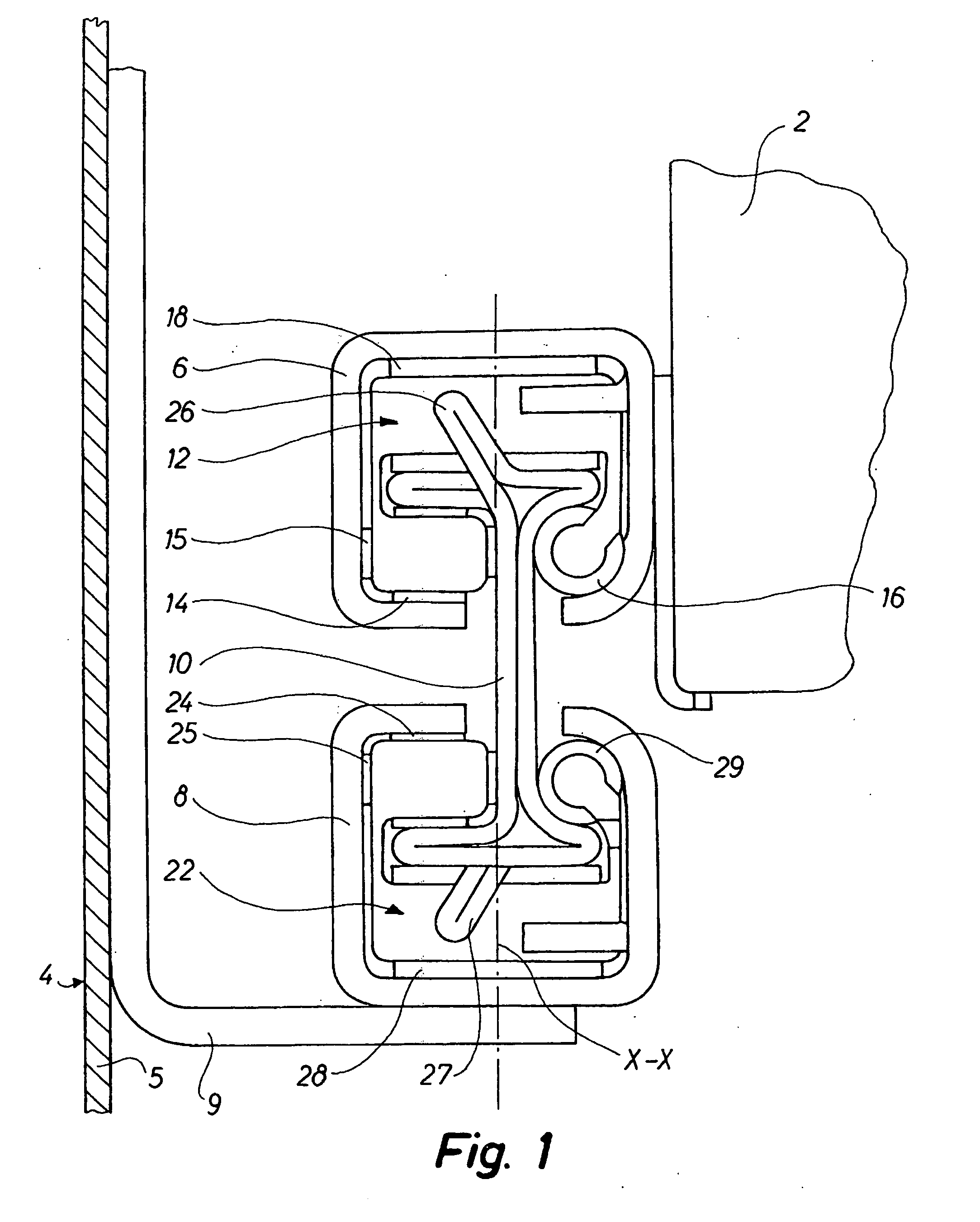
[0004]The pull-out mechanism according to the invention is characterised in that exactly one bearing ball is mounted in the part of the individual bearing holder placed on one side of the intermediate rail, whereas two rollers or wheels, the axes of which are placed in their individual planes of two planes standing perpendicular to each other, are mounted in the part of the above bearing holder, which is placed on the other side of the intermediate rail, where a substantially horizontal auxiliary roller extending to both sides of the intermediate rail is mounted in the bearing holder between the intermediate rail and the upper rail and the lower rail respectively. Hereby a considerably constructive simplification is achieved and the pull-out mechanism can bear both horizontal and vertical loads in a reliable way. Furthermore it is possible to pull out the drawer to a position just outside the actual piece of furniture.
[0007]According to the invention, incliningly extending web parts, which can serve for the fixation of the bearing holders in relation to the intermediate rail, may be provided locally on the intermediate rail. Hereby particularly good options are achieved for a reliable affixation of the bearing holders to the intermediate rail and thus a particularly reliable running of the drawer when it is pulled out or pushed in (closed).
[0008]According to a further embodiment of the invention, the intermediate rail may have a cross-section corresponding to an I, where the intermediate rail may preferably be manufactured by bending of a metal sheet, especially such that each of the webs of the intermediate rail includes two layers of metal sheets. Thereby it is achieved that the pull-out mechanism can be manufactured in a particularly simple way.
[0010]According to the invention, the individual bearing ball may have a diameter of more than 2 mm, preferably more than 3.5 mm. Thereby it is achieved that the pull-out mechanism can bear considerable weight from the drawer.

Problems solved by technology

Pairs of rollers and bearing balls are placed between the rails; the bearing balls, however, make the pull-out mechanism rather complicated and thus vulnerable.

Method used


Image

  • Pull-out mechanism for a drawer
  • Pull-out mechanism for a drawer
  • Pull-out mechanism for a drawer

Examples


Embodiment Construction

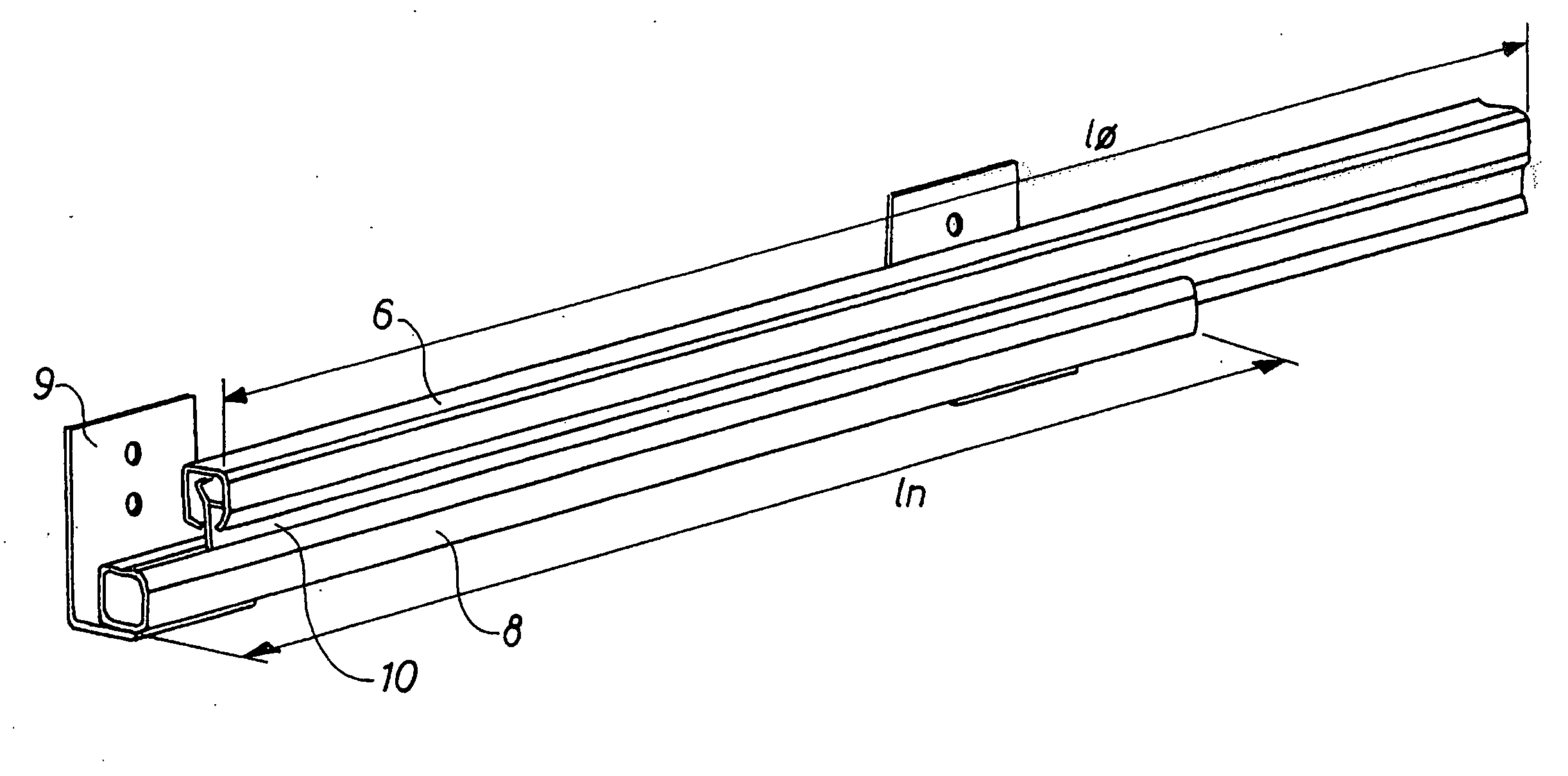
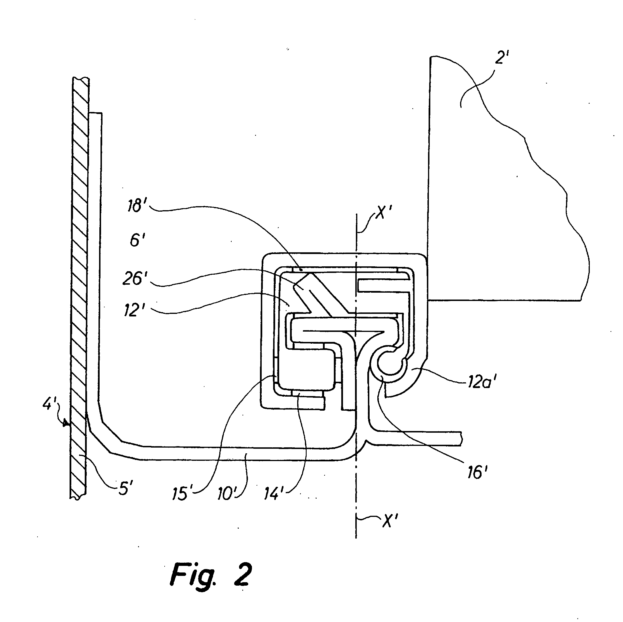
[0018]The pull-out mechanism 1 shown in FIGS. 1 and 4 is intended for mounting of a preferably big and heavy drawer 2 in a drawer cavity 3 inside a piece of furniture 4. The latter may e.g. be a filing cabinet. The pull-out mechanism 1 includes an upper pull-out rail 6, which is fastened to the drawer 2 in the longitudinal direction of the drawer (i.e. perpendicular to the plane of the paper in FIG. 1), and a lower rail 8, which is fastened to a wall 5 in the drawer cavity 3 of the piece of furniture 4 by means of fittings 9. An intermediate rail 10 is placed between the upper rail 6 and the lower rail 8, said intermediate rail being movable in its longitudinal direction, cf. FIG. 4, while it is placed between rails 6 and 8. Between the intermediate rail 10 and the upper rail 6—and at the same time to the left of the intermediate rail, especially its vertical centre plan X-X—a bearing holder 12 is inserted; possibly one or more additional bearing holders may be provided which are pl...


PUM


Abstract

A pull-out mechanism for a drawer (2) in a drawer cavity (3) in a piece of furniture (4). The pull-out mechanism includes an upper rail (8) with a substantially U-shaped cross-section, said rail being affixed to the drawer (2) in its longitudinal direction, and possibly a lower rail (8) with a substantially U-shaped cross section, said lower rail, possibly indirectly, being affixed to a wall (5) in the drawer cavity (3), and an intermediate rail (10) which in its longitudinal direction is movable between the upper rail and the lower rail. At least one bearing holder (12, 22) with roller (14, 15, 24, 25) and balls (16, 29) is inserted between the intermediate rail and the upper rail and the lower rail respectively. Exactly one bearing ball (16, 29) is mounted in the part of the individual bearing holder (12, 22) placed on one side of the intermediate rail (10); two rollers or wheels (14, 15, 24, 25) are mounted in the part of the individual bearing holder (12, 22) placed on the other side of the intermediate rail (10). The axes of rotation of said rollers or wheels are placed in each their plane of two planes standing perpendicular to each other. A substantially horizontal auxiliary roller (18, 28) extending to both sides of the intermediate rail (10) is mounted in the individual bearing holder (12, 22) between the intermediate rail (10) and the upper rail (6) and the lower rail (8) respectively. Hereby a considerably constructive simplification is achieved and the pull-out mechanism can bear both horizontal and vertical loads in a reliable way. Furthermore it is possible to pull out the drawer to a position just outside the actual piece of furniture.

Description

TECHNICAL FIELD[0001]The invention relates to a pull-out mechanism for mounting of a preferably large and heavy pull-out drawer in a drawer cavity in a piece of furniture, especially a filing cabinet, and which includes an upper rail with a substantially U-shaped cross-section, said upper pull-out rail being affixed to the drawer in the longitudinal direction of the drawer, and possibly a lower rail with a substantially U-shaped cross-section, said lower rail, possibly indirectly, being affixed to a wall in the drawer cavity, and an intermediate rail which in its longitudinal direction is movable between the upper rail and the lower rail, and where at least one bearing holder with rollers and balls is inserted between the intermediate rail and the upper rail and the lower rail respectively.BACKGROUND[0002]A mechanism is known for a drawer, where an intermediate rail is placed between an upper rail connected to a telescopic drawer and a lower rail, which is connected to the closet wh...

Claims


Application Information

Patent Timeline
IPC IPC(8): A47B88/10A47B88/493
CPCA47B88/10A47B2210/001A47B2210/0032A47B2210/0059A47B2210/0043A47B2210/0056A47B2210/0037A47B88/493
Inventor JOHANSSON, TOBIAS
Owner INTER IKEA SYST
Learn More