Robust current mirror with improved input voltage headroom

a current mirror and input voltage technology, applied in the direction of automatic control, process and machine control, instruments, etc., can solve the problem of very limited implementation headroom, achieve simple design implementation, improve input voltage headroom, and maintain performance over process variations

Inactive Publication Date: 2010-02-04
AVAGO TECH WIRELESS IP SINGAPORE PTE
View PDF5 Cites 0 Cited by
  • Summary
  • Abstract
  • Description
  • Claims
  • Application Information

AI Technical Summary

Benefits of technology

[0017]The objects, features and advantages of the present invention include providing an integrated current mirror circuit that may (i) overcome one or more disadvantages of conventional designs, (ii) improve input voltage headroom, (iii) provide a simple design to implement, (iv) maintain performance over process variations, and / or (v) be feasible to implement in low voltage supply applications.

Problems solved by technology

Such an implementation has very limited headroom and has problems when the PN junction of the MOSFET M3 is turned on.
Even when adjusting the bias voltage Vb, the circuit 20 faces other problems.

Method used


Image

  • Robust current mirror with improved input voltage headroom
  • Robust current mirror with improved input voltage headroom
  • Robust current mirror with improved input voltage headroom

Examples


Embodiment Construction

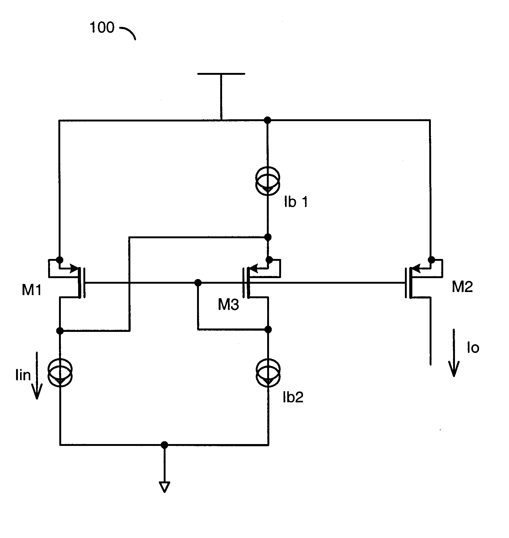
[0024]With technology scaling, transistors and supply voltages are continuing to get smaller. Circuit designs relating to low voltage supply applications are becoming more important. One embodiment of the present invention concerns Integrated Circuits (ICs) and more particularly to low voltage analog applications that use current mirror circuits. One embodiment of the present invention concerns an integrated current mirror circuit that overcomes the disadvantages of conventional designs while improving input voltage headroom.

[0025]Referring to FIG. 3, a diagram of a circuit 100 illustrating an embodiment of the present invention is shown. The circuit 100 may maintain performance over process variations. The circuit 100 may be feasible to implement in low voltage supply applications. The circuit 100 generally comprises a transistor M1, a transistor M2, a transistor M3, a current source Ib1, a current source Ib2 and a current source Iin. The circuit 100 may be implemented, in one exam...


PUM


Abstract

An apparatus comprising an input current source device, a first transistor, a second transistor and a level shifter device. The input current source device may provide a input current source. The first transistor may be configured to operate in saturation for mirroring the input current source to an output current source. The first transistor may have (i) a source node connected to a supply, and (ii) a drain connected to the input current source. The second transistor may also be configured to operate in saturation. The second transistor may have (i) a gate connected to a gate of the first transistor, (ii) a source connected to the supply, and (iii) a drain configured as an output current node. The level shifter device may comprise a third transistor, a first bias current source and a second bias current source.

Description

FIELD OF THE INVENTION[0001]The present invention relates to current mirror circuits generally and, more particularly, to a method and / or apparatus for implementing a robust current mirror with improved input voltage headroom.BACKGROUND OF THE INVENTION[0002]Referring to FIG. 1, a conventional current mirror circuit 10 is shown. The circuit 10 includes a MOSFET M1, a MOSFET M2, an input current Iin, and an output current Io. The MOSFET M1 is connected as a diode that operates in saturation. The MOSFET M1 has a channel that carries the input current Iin. The MOSFET M2 also operates in saturation. The MOSFET M2 has a channel that carries the output current Io. The gates of the MOSFET M1 and the MOSFET M2 are connected together to ensure identical control voltages (i.e., gate to source voltages). Identical control voltages on the MOSFET M1 and the MOSFET M2 results in the input current Iin being mirrored to the output current Io. The ratio of the input current to the output current (Io...

Claims


Application Information

Patent Timeline
Patent Type & Authority Applications(United States)
IPC IPC(8): H03L5/00
CPCG05F3/262
Inventor WANG, DONGHUI
Owner AVAGO TECH WIRELESS IP SINGAPORE PTE
Why Eureka
Try Eureka