CCTV Camera Lens Adjustment Structure

a technology for the lens, which is applied in the field of adjusting the structure of the camera lens, can solve the problems of inconvenience during adjustment, the index finger cannot pass through, and the adjustment procedure and assembly work are complicated, and achieve the effect of convenient us

Inactive Publication Date: 2010-02-04
CHANG HAI CHIN
View PDF18 Cites 7 Cited by
  • Summary
  • Abstract
  • Description
  • Claims
  • Application Information

AI Technical Summary

Benefits of technology

[0004]The main purpose of the present invention is to make use of the matching between housing and adjustment mechanism to enable imaging capturing unit with ease in installation and waterproof effect and to make use of the adjustment mechanism to rotate the driving ring of the linking lens so as to rotate the lens of image capturing lens outside the housing in order to achieve the convenience in use.

Problems solved by technology

Hence leading to the complexity in adjustment procedure and assembly work, resulting in inconvenience during adjustment.
Some openings even could only allow the index finger to pass through.
Thus not only resulting in difficulty during adjustment but also worrying in cutting fingers due to the sharp edges formed by the material in the opening for the housing.
Again, as there is an opening installed on the housing and the CCTV camera is usually installed outdoors, rain tends to enter the housing through the opening during rainy days, resulting in the damage to the image capturing unit.

Method used


Image

  • CCTV Camera Lens Adjustment Structure
  • CCTV Camera Lens Adjustment Structure
  • CCTV Camera Lens Adjustment Structure

Examples


Embodiment Construction

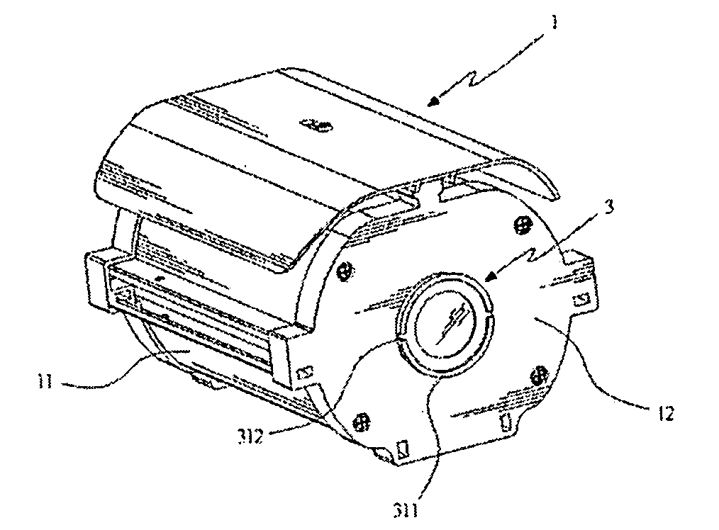
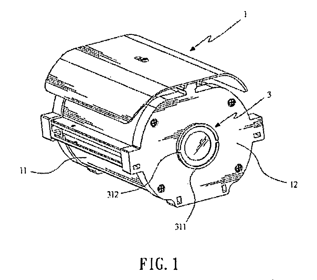
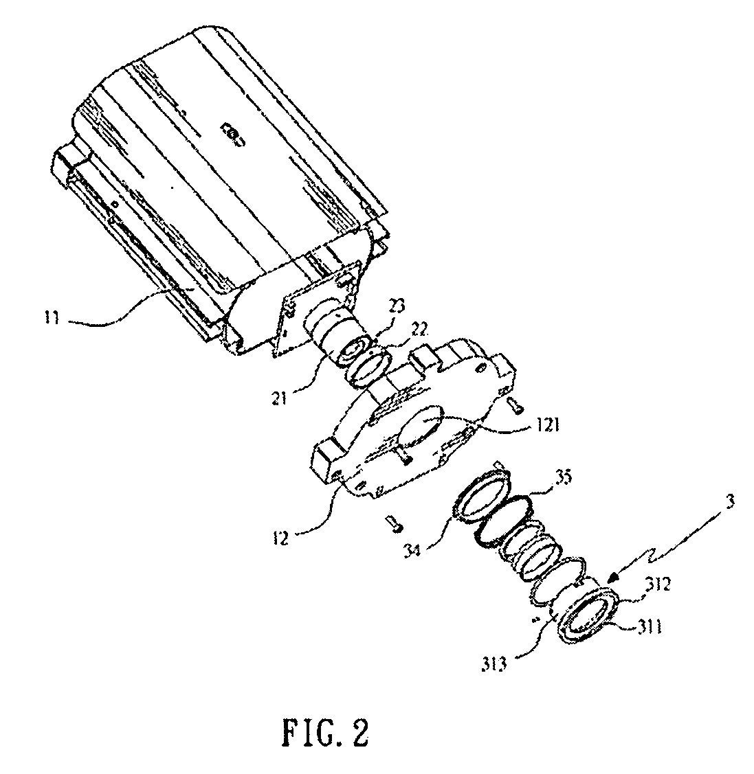
[0011]Please refer to the diagrams shown in FIGS. 1, 2, and 3 which are the illustration of the outlook of the present invention, the exploded diagram of the present invention, and the exploded diagram of the adjustment mechanism of the present invention. As shown in these diagrams, the present invention is an improved adjustment mechanism of the lens of the CCTV camera consisting of at least a housing 1, an image capturing unit 2, and an adjustment mechanism 3.

[0012]The housing 1 mentioned above contains at least a shell 11 and a cover 12 installed on the side of the shell 11 and with a through hole 121.

[0013]The said image capturing unit 2 is installed in the shell 11 mentioned above wherein one end has a lens 21 corresponding to the through hole 121 installed in the cover 12; the said lens 21 is installed with a driving ring 22; the said driving ring 22 is fixed on the lens 21 by matching the fixed rod 23; and the said fixed rod 23 partially extends out the driving ring 22 and sa...


PUM


Abstract

The present invention relates to an improved CCTV camera lens adjustment structure comprising a housing with a shell and a cover, wherein the shell has a through hole; an image capturing unit installed in the shell, wherein one end is a lens corresponding to the hole installed on the shell; the lens is installed with a driving ring, said driving ring matches the fixed rod installed on the lens; said fixed rod is partially extended as driving ring; and a movable adjusting mechanism installed in the hole forming interference with fixed rod. Thus the matching of the shell and the adjustment structure is used for the image capturing unit to achieve the effect of ease in installation and waterproof, and the adjustment mechanism can be used to rotate the driving ring of the linked lens for rotating the lens of image capturing unit so as to achieve the convenience in use.

Description

FIELD OF THE INVENTION[0001]The present invention relates to an improved CCTV camera lens adjustment structure, particularly a kind of image capturing unit for achieving ease in installation and waterproof effect and for the adjustment of focus of the lens from outside to achieve convenience in use.BACKGROUND OF THE INVENTION[0002]Traditionally the CCTV camera consists of at least a housing and an image capturing unit installed in the housing, wherein the image capturing unit comprises a lens corresponding to one side of the housing and the housing is made of metallic material, its bottom has an opening corresponding to the outer edge of the bottom of the lens, and the opening is installed with a cover matching several fixing parts; thus it constitutes a lens installed in a desired location for the capturing of image concerned. When the focus of the lens is required for adjustment, the cover at the bottom of the shell can be removed and the hand could reach inside through the openin...

Claims


Application Information

Patent Timeline
Patent Type & Authority Applications(United States)
IPC IPC(8): H04N5/225
CPCG03B17/08H04N5/2254H04N5/2252H04N23/55H04N23/51
Inventor CHANG, HAI-CHIN
Owner CHANG HAI CHIN
Why Eureka
Try Eureka