Customer replaceable unit monitor (CRUM) unit, replaceable unit and image forming apparatus comprising the crum unit, and unit driving method thereof

a technology of monitors and monitors, which is applied in the direction of electrographic process apparatus, instruments, optics, etc., can solve the problems of inability to produce good quality images, rollers or belts may wear out or deteriorate, and cannot render high-quality printouts at the end of their lives, so as to achieve the effect of reducing computational load

Active Publication Date: 2010-02-04
HEWLETT PACKARD DEV CO LP
View PDF8 Cites 13 Cited by
  • Summary
  • Abstract
  • Description
  • Claims
  • Application Information

AI Technical Summary

Benefits of technology

[0034]As a result, each of the at least one replaceable unit can be driven under the optimum driving condition, to minimize computational load.

Problems solved by technology

In addition to the ink or toner unit mentioned above, the replaceable unit includes other units which are not exhausted, but may deteriorate from use or over time and thus cannot render high quality printouts at the end of their lives.
For example, a laser image forming apparatus employs an electric charging unit, a transfer unit, and a fusing unit therein, and in each of the units, rollers or belts may wear out or deteriorate over time.
Therefore, a good quality image cannot be produced.
However, due to several limitations of the replaceable units, such as limited structure or a need to interface with the main controller in the image forming apparatus, thermistors are installed in a few limited places and cannot check the temperature accurately.
In addition, since detected temperatures can have different values depending on the places where the thermistors are installed, it is also difficult to determine the optimum driving conditions of the replaceable units accurately.
Furthermore, since the main controller is required to control an image forming process based on the temperature checks received from the thermistors, the main controller can have increased computational load, and thus can be delayed in carrying out control programs.

Method used


Image

  • Customer replaceable unit monitor (CRUM) unit, replaceable unit and image forming apparatus comprising the crum unit, and unit driving method thereof
  • Customer replaceable unit monitor (CRUM) unit, replaceable unit and image forming apparatus comprising the crum unit, and unit driving method thereof
  • Customer replaceable unit monitor (CRUM) unit, replaceable unit and image forming apparatus comprising the crum unit, and unit driving method thereof

Examples


Embodiment Construction

[0046]Reference will now be made in detail to exemplary embodiments of the present general inventive concept, examples of which are illustrated in the accompanying drawings, wherein like reference numerals refer to the like elements throughout. The exemplary embodiments are described below in order to explain the present general inventive concept by referring to the figures.

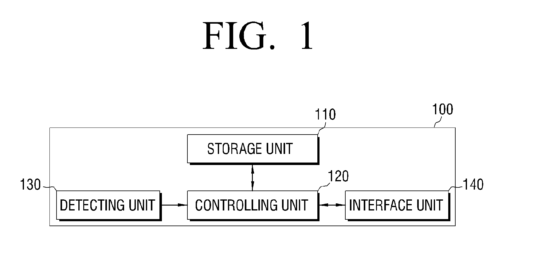
[0047]FIG. 1 illustrates a block diagram of a replaceable unit 100 according to an exemplary embodiment of the present general inventive concept. The ‘replaceable unit’ herein refers to a unit which is provided inside the image forming apparatus, to participate in an image forming job, and which is replaceable by a user or a manufacturer. For example, the replaceable unit 100 may include a developing unit, a charging unit, a transfer unit, a fusing unit, an organic photo conductor (OPC), a laser scanning unit (LSU), a paper feeding roller, or a feeding roller.

[0048]Referring to FIG. 1, the replaceable unit 100 in...


PUM


Abstract

A replaceable unit to participate in an image forming job of an image forming apparatus includes a storage unit to store therein a driving condition corresponding to an operation environment, a detecting unit to monitor the operation environment, a controlling unit to detect a corresponding driving condition from the storage unit if the detecting unit detects the driving environment, and an interface unit to provide a main body of the image forming apparatus with the detected corresponding driving condition. Accordingly, the replaceable unit can be driven under optimum driving conditions.

Description

CROSS-REFERENCE TO RELATED APPLICATIONS[0001]This application claims priority under 35 U.S.C. § 119(a) from Korean Patent Application No. 10-2008-0075266, filed on Jul. 31, 2008, in the Korean Intellectual Property Office, the disclosure of which is incorporated herein by reference in its entirety.BACKGROUND OF THE INVENTION[0002]1. Field of the Invention[0003]The present general inventive concept relates to a customer replaceable unit monitor (CRUM) unit, and a replaceable unit and an image forming apparatus comprising the CRUM unit, and a unit driving method thereof. More particularly, the present general inventive concept relates to a CRUM unit and a replaceable unit capable of computing driving conditions individually, an image forming apparatus for driving the replaceable unit based on the computed driving conditions, and a unit driving method thereof.[0004]2. Description of the Related Art[0005]The use of computers and computer components such as printers, scanners, copiers, o...

Claims


Application Information

Patent Timeline
Patent Type & Authority Applications(United States)
IPC IPC(8): G03G15/00
CPCG03G21/20G03G15/00
Inventor LEE, JAE-SUNGKIM, YONG-GEUNLEE, YOON-TAE
Owner HEWLETT PACKARD DEV CO LP
Why Eureka
Try Eureka