System for transferance of test tubes from tube rack to centrifuge rotor

a technology of centrifuge rotor and transfer tube, which is applied in the field of system for controlling and maintaining vessels, can solve the problems and achieve the effect of saving user significant effort and tim

Inactive Publication Date: 2010-02-11
SHERMAN YURY +2
View PDF2 Cites 15 Cited by
  • Summary
  • Abstract
  • Description
  • Claims
  • Application Information

AI Technical Summary

Benefits of technology

[0009]According to one embodiment of the present invention, test tubes are placed in distinct vertical openings, one opening for one tube, of the tube holder. The entire holder may then be placed on a rack that may provide for linear or non-linear storage by means of a shoulder that is integral to the holder. The centrifuge may also include a docking mechanism that is also compatible with the shoulder. The docking mechanism then allows for placement of the holder within the centrifuge where centrifugation may take place. After centrifug...

Problems solved by technology

This saves the user s...

Method used


Image

  • System for transferance of test tubes from tube rack to centrifuge rotor
  • System for transferance of test tubes from tube rack to centrifuge rotor
  • System for transferance of test tubes from tube rack to centrifuge rotor

Examples


Embodiment Construction

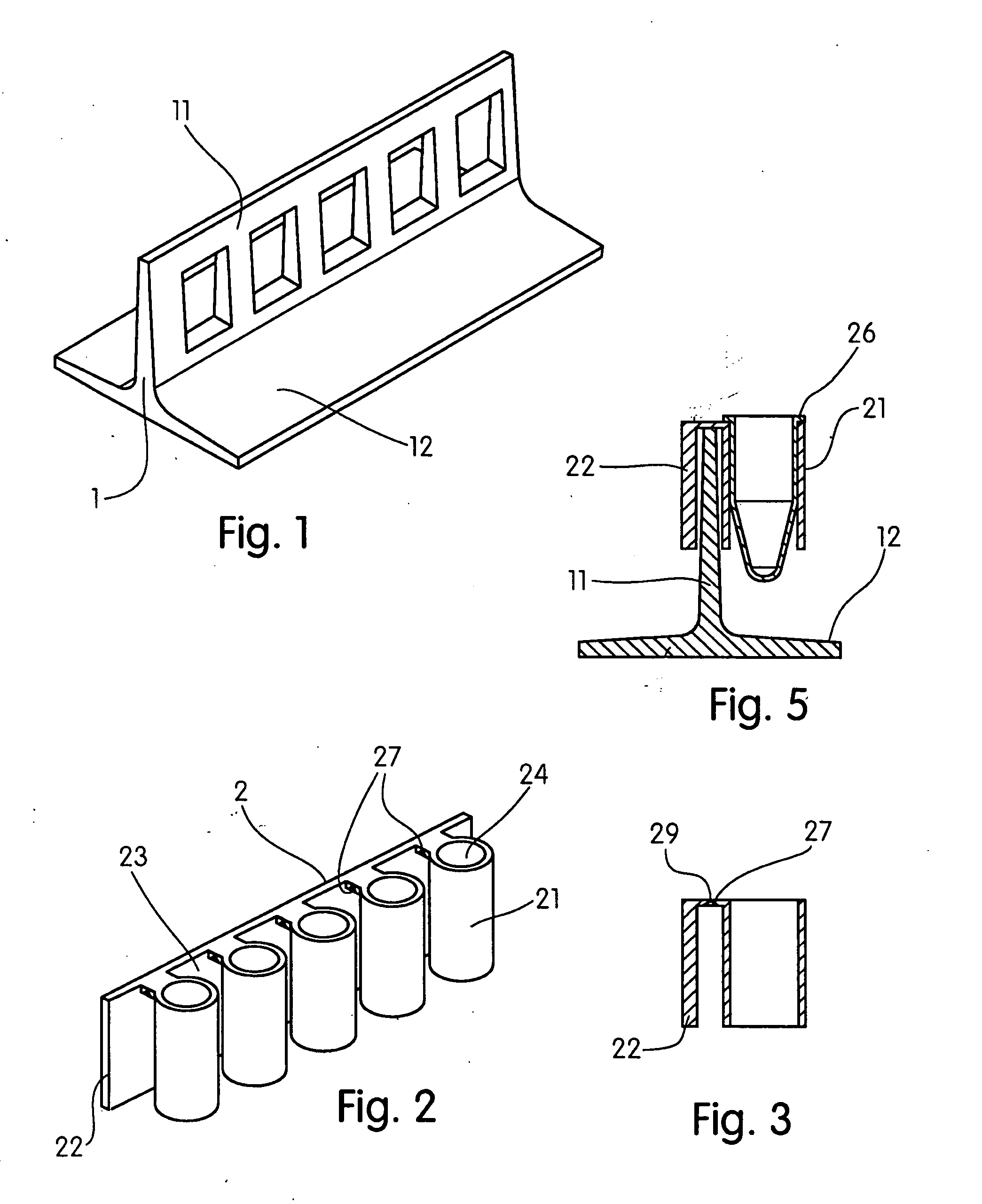
[0023]In FIG. 1 rack 1, having substantially linear wall 11 and supporting pad 12 providing stability of the rack, are shown. Thickness and length of wall 11 is suitable for coupling a removable tube holder 2, FIG. 2.

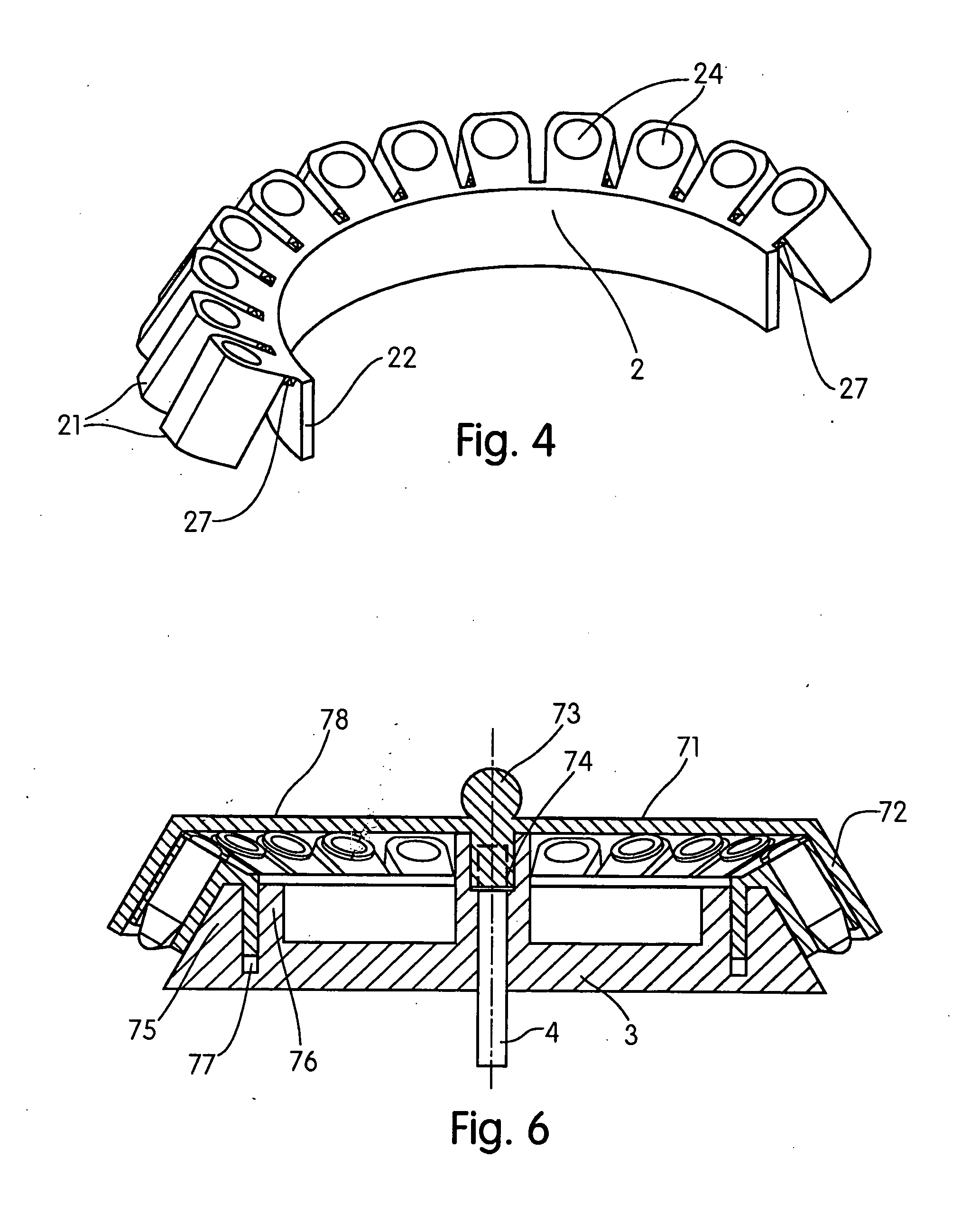
[0024]In FIG. 2, a portion of tube holder 2 is shown comprising a plurality of tube cells 21 and shoulder 22. Each tube cell 21 has portions defining an aperture 24 capable of accommodate a test tube. The tube holder 2 also comprises portions defining cell gaps 23 between the pluralities of tube cells 21, which may provide angular displacement of adjacent tube cells 21 when shoulder 22 deformed in an angular manner. Shoulder 22 is integrated with the tube cells 21 by connecting member 29 located at a top portion of the tube holder 2, as shown in FIG. 3. The connecting member 29 includes living hinges 27 along shoulder 22, providing angular displacements of cells 21 about the shoulder. Thus, when the shoulder 22 is bent, cells 21 are able to take a shape shown in FIG. 4 ...


PUM


Abstract

The present invention includes a system and method for the management of specimens ordinarily manipulated via tubes. The invention may include a flexible, removable tube holder that is linear when placed in a rack and curved when placed into a centrifuge rotor. The system provides for the elimination of manual recording of the individual tubes, and also provides for the transference of the tubes from the rack to the centrifuge and back in a group.

Description

BACKGROUND OF THE INVENTION[0001]1. Field of the Invention[0002]The present invention relates generally to the field of scientific research, and more particularly to a system for controlling and maintaining vessels used in scientific research.[0003]2. Description of the Related Art[0004]Scientific research, and more particularly biomedical research, often requires the separation of fractions in complex mixtures by centrifugation. This is a very widespread procedure both in biomedical research and general clinics. Often this procedure is performed with multiple receptacles, such as test tubes. An example of the procedure utilized may be summarized as follows: the tubes are placed in a rack and filled with various solutions and mixtures (generally “media”), for example cell or tissue lysates or similar material that are to be subjected to homogenization, mixing, resuspension, or other treatments; the tubes with media are taken from the rack and manually placed in a centrifuge rotor; n...

Claims


Application Information

Patent Timeline
IPC IPC(8): B01L9/06B04B5/02
CPCB01L3/5021B01L9/06B01L2300/043B04B2005/0435B01L2400/0409B04B5/0414B01L2300/123
Inventor SHERMAN, YURYSHERMAN, MICHAELGLASGOW, IAN
Owner SHERMAN YURY
Why Eureka
Try Eureka