Energy Device With Integral Collector Surface For Electromagnetic Energy Harvesting And Method Thereof

a technology of electromagnetic energy and energy device, which is applied in the direction of sustainable manufacturing/processing, greenhouse gas reduction, and final product manufacturing, etc., to achieve the effects of enhancing the directional reception characteristics, and enhancing the efficiency and/or capacity of energy collection

Inactive Publication Date: 2010-02-11
SAPURAST RES
View PDF101 Cites 50 Cited by
  • Summary
  • Abstract
  • Description
  • Claims
  • Application Information

AI Technical Summary

Benefits of technology

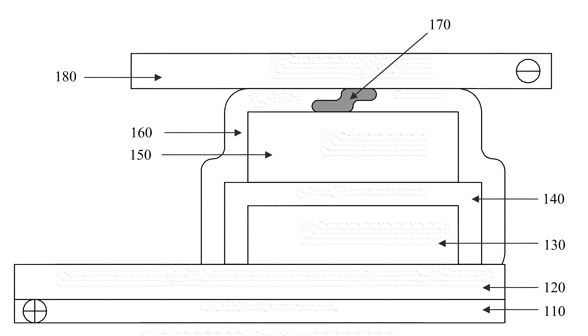
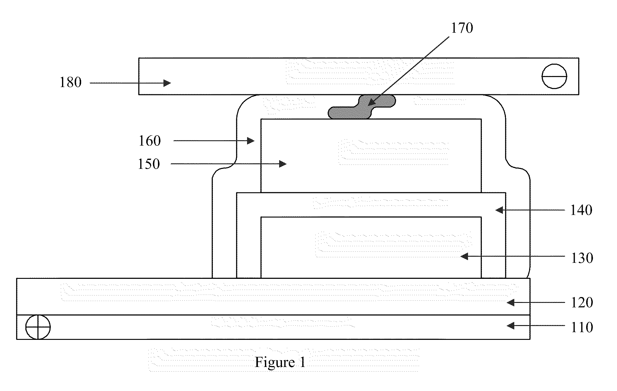
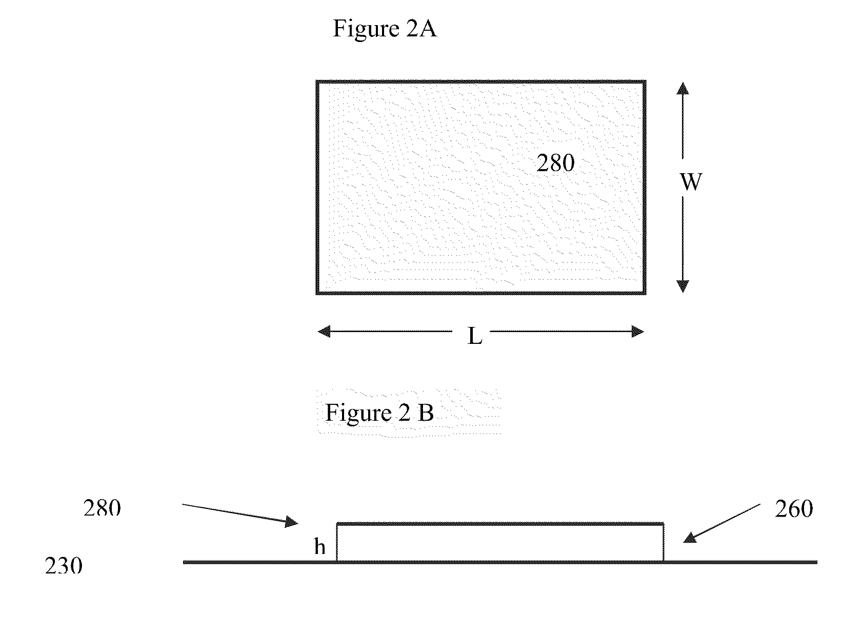
[0011]Added features, patterns, or shapes may be applied to the conductive surface of an energy device to increase efficiency and / or capacity in energy collection for a specific frequency band, broad band, or other energy applications. For flexible devices, the integral conductive surface may, for example, be curved (e.g., z-axis displacement) to enhance its energy collecting capabilities or to enhance its directional reception characteristics.

Problems solved by technology

Generally, systems that collect electromagnetic energy, such as antennas for example, are only designed to capture the information that is being transmitted through the electromagnetic medium and generally do not capture a substantial portion of the energy itself.

Method used


Image

  • Energy Device With Integral Collector Surface For Electromagnetic Energy Harvesting And Method Thereof
  • Energy Device With Integral Collector Surface For Electromagnetic Energy Harvesting And Method Thereof
  • Energy Device With Integral Collector Surface For Electromagnetic Energy Harvesting And Method Thereof

Examples


Embodiment Construction

[0025]It is to be understood that the present invention is not limited to the particular methodology, compounds, materials, manufacturing techniques, uses, and applications described herein, as these may vary. It is also to be understood that the terminology used herein is used for the purpose of describing particular embodiments only, and is not intended to limit the scope of the present invention. It must be noted that as used herein and in the appended claims, the singular forms “a,”“an,” and “the” include the plural reference unless the context clearly dictates otherwise. Thus, for example, a reference to “an element” is a reference to one or more elements, and includes equivalents thereof known to those skilled in the art. Similarly, for another example, a reference to “a step” or “a means” is a reference to one or more steps or means and may include sub-steps or subservient means. All conjunctions used are to be understood in the most inclusive sense possible. Thus, the word “...


PUM


Abstract

An apparatus, method, and system to harvest and store electromagnetic energy is disclosed. The present invention uses, for example, conductive surfaces within the energy storage component itself as a means of electromagnetic energy collection. The surface may be an integral portion of the energy device, such as a charge collection surface within a battery or a capacitor that mainly provides the battery or a capacitor with a necessary function. In another embodiment of the invention a metallic or conductive surface is added to and specifically built into the energy device during manufacturing for the main purpose of collecting electromagnetic energy for the energy device but is otherwise not necessary for the energy storage component. Once the energy is collected, it can be rectified either via rectification components that were built directly into the energy storage component during its manufacture or connected external to the energy storage component but within the energy device. The so-designed energy device may represent a self-sustaining, autonomous electromagnetic energy harvesting—energy storage device.

Description

RELATED APPLICATIONS[0001]This application is related to and claims the benefit under 35 U.S.C. §119 of U.S. Provisional Patent Application Ser. No. 61 / 087,927, entitled “Energy Device with Integral Collector Surface for Electromagnetic Energy Harvesting and Method Thereof,” filed on Aug. 11, 2008, which is incorporated herein by reference in its entirety.TECHNICAL FIELD AND BACKGROUND OF THE INVENTION[0002]This invention relates to an apparatus and / or a system or method of harvesting energy. In particular, the present invention collects electromagnetic energy that exists in the ambient environment or that is intentionally directed to an energy harvesting device and stores said energy for later use.[0003]Electromagnetic energy exists in all sorts of forms. It is generally used to transmit information, but also exists, albeit typically small, as a source of energy which may be collected and stored.[0004]Generally, systems that collect electromagnetic energy, such as antennas for exam...

Claims


Application Information

Patent Timeline
Patent Type & Authority Applications(United States)
IPC IPC(8): H01L31/042H01L31/02H01L31/0203H01L31/0236
CPCH01L31/022425H01L31/042H01M10/46H01M10/465Y02E60/12H02J7/0042H02J17/00H02J7/025Y02E10/50H02S40/38H01Q1/248H01Q1/44H02J50/001H02J50/27Y02E60/10Y02E70/30Y02P70/50H02J50/402H02J50/30H02J50/005
Inventor BRANTNER, PAUL C.
Owner SAPURAST RES
Why Eureka
Try Eureka