Grain cleaning unit with cleaning airstream vented above grain pan for a combine harvester

a combine harvester and cleaning unit technology, applied in the direction of cleaning process and equipment, solid separation, agriculture tools and machines, etc., can solve the problems of inhibiting the full potential of modern separating technology, the development of threshing and separating technology of recent years, and the inability to match the development of cleaning unit capacity, so as to enhance the lifting effect, enhance the stratification effect, and the effect of increasing the separating

Inactive Publication Date: 2017-08-01
AGCO AS
View PDF40 Cites 1 Cited by
  • Summary
  • Abstract
  • Description
  • Claims
  • Application Information

AI Technical Summary

Benefits of technology

[0010]It is an object of the invention to provide an improved grain cleaning apparatus in a combine harvester to increase the efficiency and / or capacity of the cleaning unit.

Problems solved by technology

Developments in threshing and separating technology of recent years have not been matched by an increase in capacity of the cleaning unit.
The bottleneck presented by the cleaning unit therefore inhibits utilisation of the full potential of modern separating technology.

Method used


Image

  • Grain cleaning unit with cleaning airstream vented above grain pan for a combine harvester
  • Grain cleaning unit with cleaning airstream vented above grain pan for a combine harvester
  • Grain cleaning unit with cleaning airstream vented above grain pan for a combine harvester

Examples


second embodiment

[0057]FIGS. 8 to 11 illustrate the invention in which the second cleaning air stream Y is generated by dedicated additional fans separate from that which generates the first cleaning air stream. Like reference numerals will be applied to those features which are common between the two embodiments.

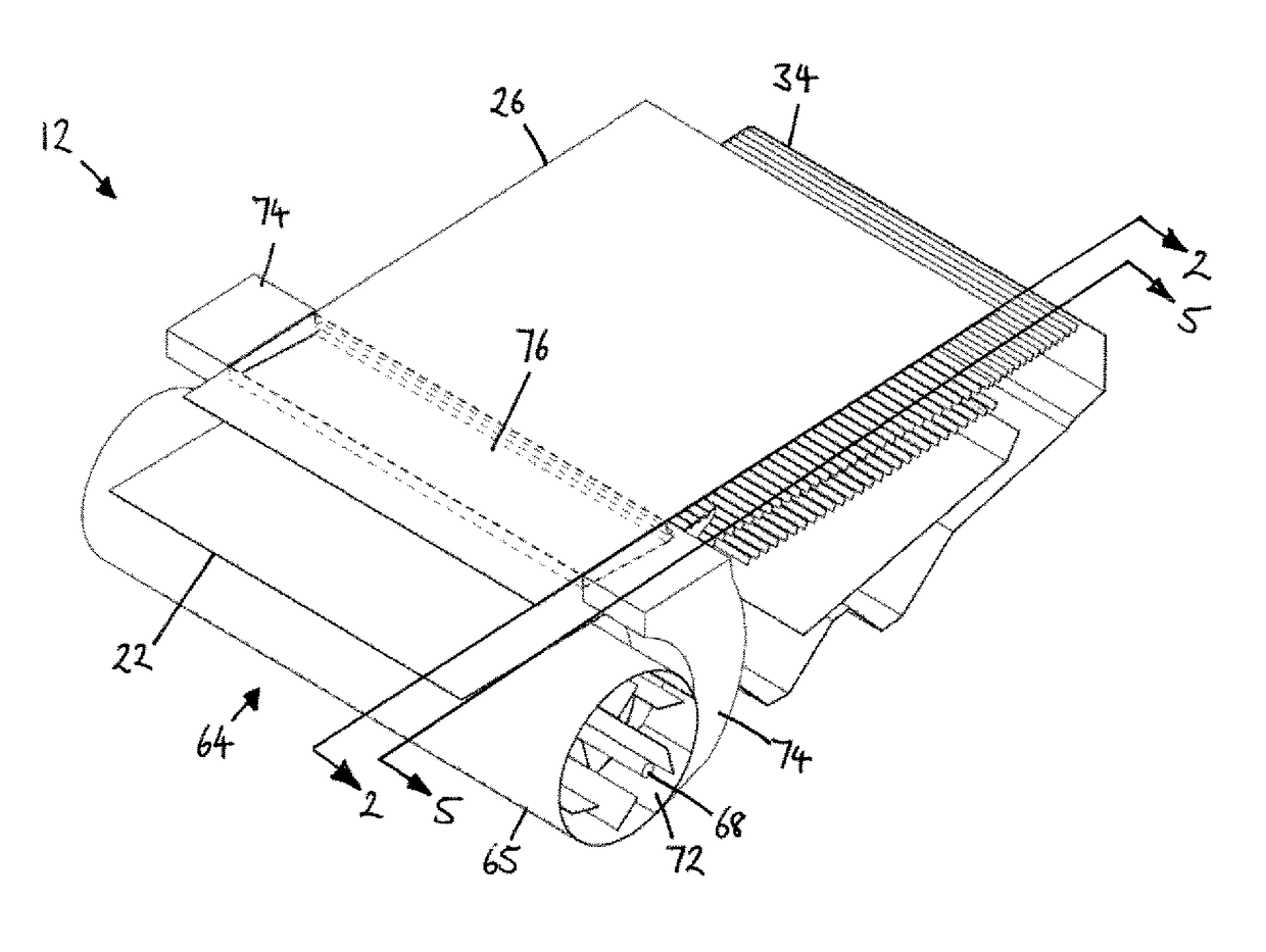
[0058]Grain cleaning apparatus 112 includes a fan unit 130 having a central fan housing 132 and two auxiliary fan housings 133,134 sharing the same axis as central housing 132 but separated therefrom by a respective gap 144. Central fan housing 132 houses a main fan 46 having a fan shaft 68 and impeller blades 50 driven thereby. Central fan housing 132 includes an opening on its rear side which is communication with a central duct 52 having a similar construction to that described with reference to FIGS. 2 to 7 above. Main fan 46 serves to generate a first cleaning air stream X which is directed under the rear edge 22R of grain pan 22 as above.

[0059]Each auxiliary fan housing 133, 134 house...

third embodiment

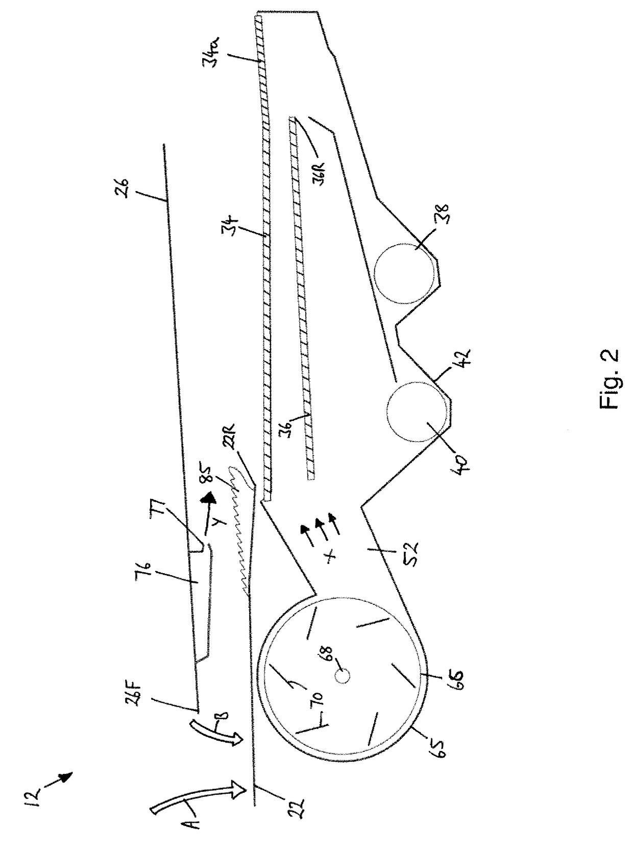
[0062]FIG. 12 illustrates the invention in which the second cleaning air stream Y of grain cleaning apparatus 212 is directed into the volume above the grain pan 22 by a pair of air nozzles 275, 276 which are mounted independently of the separator pan 26. Advantageously, the air nozzles 275, 276 are not subject to the vigorous oscillation of the separator pan 26 and, therefore, do not require a flexible connection to the source. The nozzles 275, 276 are spaced with sufficient clearance from the separator pan 26 and grain pan 22 so as not to interfere with the operation thereof.

[0063]The nozzles 275, 276 are angled so that the two air streams combine to create a generally linear airflow across the top of the grain pan 22 in a generally rearward direction.

[0064]In summary there is provided a combine harvester comprising threshing apparatus, a grain pan and a cleaning unit. The grain pan is arranged to collect a grain / chaff stream from the threshing apparatus and is driven in an oscill...


PUM


Abstract

A combine harvester includes threshing apparatus, a grain pan and a cleaning unit. The grain pan is arranged to collect a grain / chaff stream from the threshing apparatus and is driven in an oscillating manner to convey the collected grain / chaff to a rear edge from where the grain / chaff stream falls into the cleaning unit. The cleaning unit includes a fan unit for generating an airstream directed through the grain / chaff stream falling from the rear edge and an airstream vented above the grain pan.

Description

FIELD OF THE INVENTION[0001]The invention relates to the processing of a crop stream in a combine harvester and more particularly to the processing and cleaning of grain separated by threshing apparatus.BACKGROUND[0002]For many decades, self-propelled combine harvesters have been used by farmers to harvest a wide range of crops including cereals, maize and oil-seed rape. Typically, a combine harvester cuts the crop material, threshes the grain therefrom, separates the grain from the straw, and cleans the grain before storing in an on-board tank. Straw and crop residue is ejected from the rear of the machine.[0003]Threshing is typically carried out by one or more threshing cylinders which rotate within a drum or cage. Combines of the conventional or hybrid threshing type comprise a threshing cylinder which rotates on a transverse axis wherein the crop material passes tangentially under the cylinder. An axial-type threshing system includes one or more rotors having longitudinally-alig...

Claims


Application Information

Patent Timeline
Patent Type & Authority Patents(United States)
IPC IPC(8): A01F12/48B07B1/55B08B5/00A01F12/44A01F7/04
CPCA01F12/444A01F7/04A01F12/448A01F12/48
Inventor BILDE, MORTEN LETH
Owner AGCO AS
Why Eureka
Try Eureka