Monitoring System

a monitoring system and monitoring technology, applied in the direction of optical detection, sensors, diagnostics, etc., can solve the problems of not being able to administer the highest possible level of personal physical care and support, affecting the movement of carer or carer about the furniture, and heightened risk of not being able to subsequently enabl

Inactive Publication Date: 2010-02-11
CONSENG
View PDF24 Cites 21 Cited by
  • Summary
  • Abstract
  • Description
  • Claims
  • Application Information

AI Technical Summary

Benefits of technology

[0014]It is an object of the present invention to overcome or at least ameliorate at least one of the disadvantages of the prior art, or to provide a useful alternative.

Problems solved by technology

Due to costs and resource limitations there are typically many more patients requiring care than there are carers—such as nurses or other health service professionals—in any given organisation.
Therefore, it is not always possible to administer the highest possible level of personal physical care and support to each and every patient that may warrant attention.
These types of methodologies are specifically designed for a given installation or application and suffer from one or more common disadvantages such as:Presenting a physical barrier to movement of the patient and potentially entrapping a patient and otherwise impinging upon their legal freedoms.Providing a high incidence of false alarms.Being a safety hazard.Mechanically or electrically unreliable.Having a short operational lifetime.Posing hygiene problems for patients.Typically trigger once the patient completed or almost completed movement from a bed or chair to the floor.
This considerably hinders movement of the carer or carers about the furniture or room unless the monitoring system is disabled.
And where it is necessary to regularly disable a monitoring system there is a heightened risk that it will not be subsequently enabled.
Moreover, such systems are often expensive to commission, operate and replace.

Method used


Image

  • Monitoring System
  • Monitoring System
  • Monitoring System

Examples


Embodiment Construction

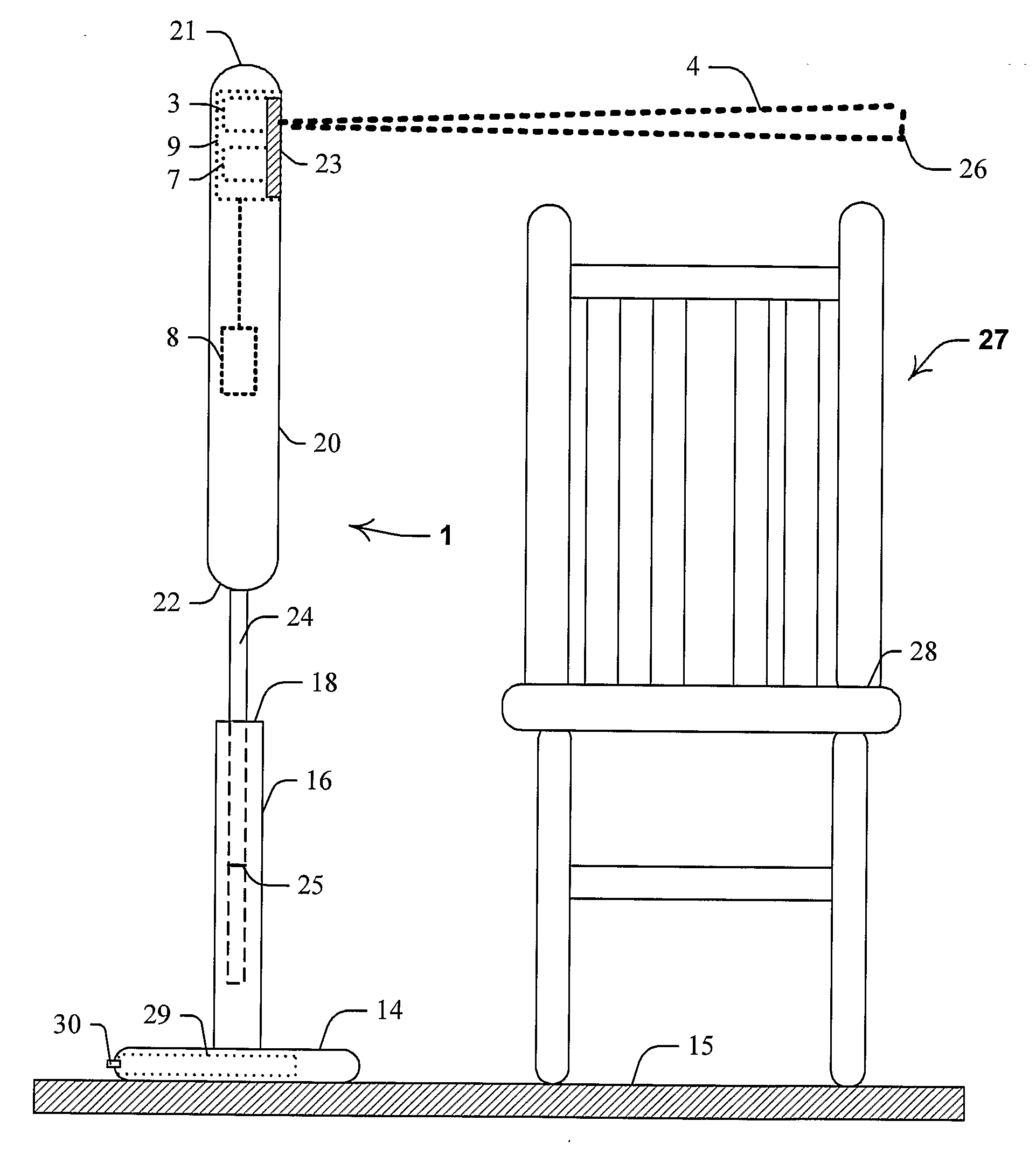
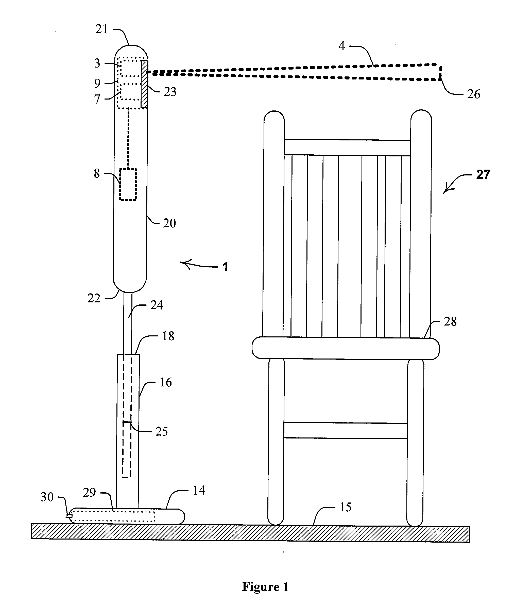
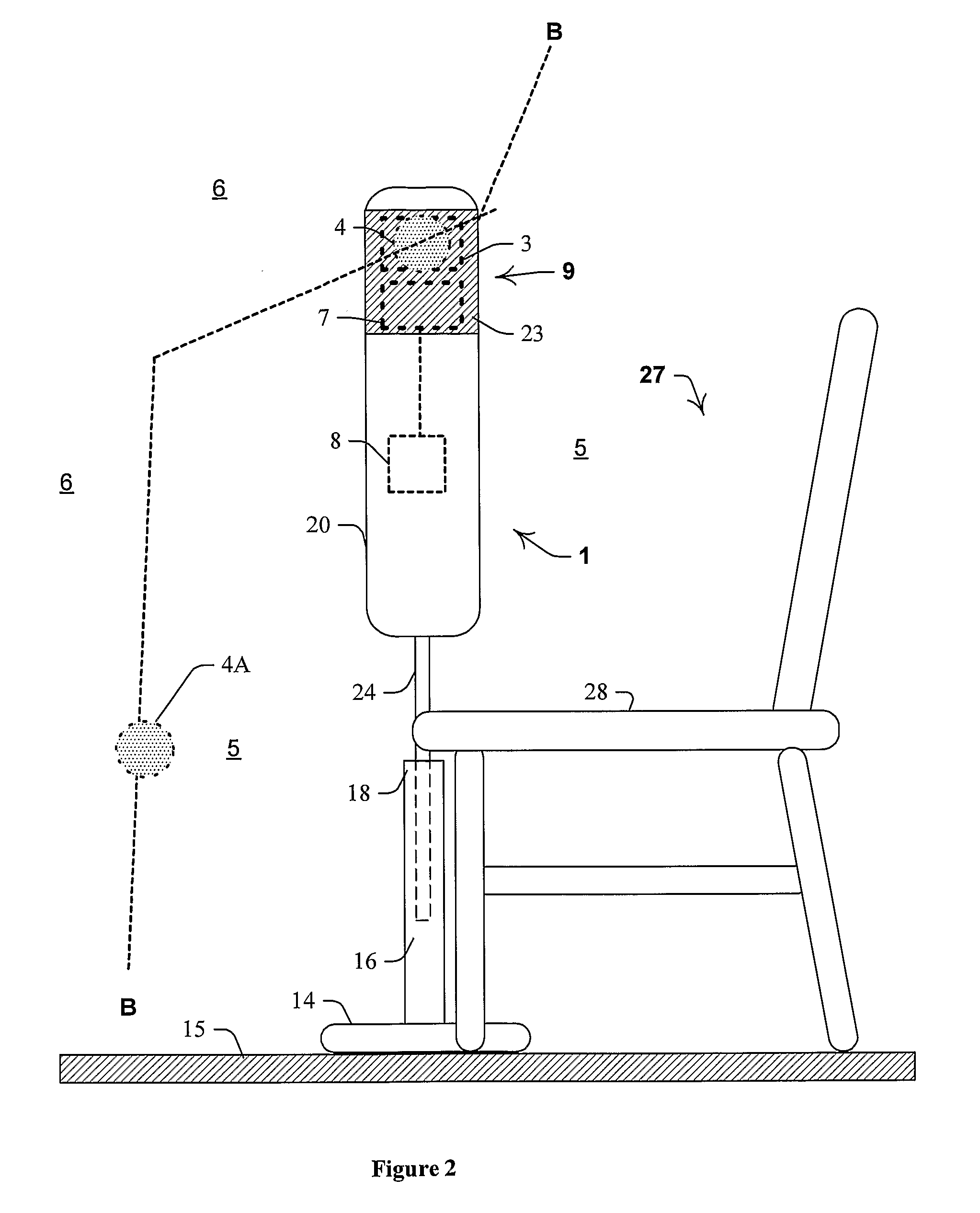
[0130]Referring to FIGS. 1 to 3, and in particular to FIG. 1, there is illustrated a self-contained portable freestanding monitoring unit 1 for an individual in the form of a human patient (not shown) in an aged-care facility 2. Unit 1 includes a transmitter 3 for generating a diffuse infrared field 4 that is indicated schematically and generally by broken lines. As best illustrated in FIG. 2, field 4 defines at least part of a boundary B-B between a first region—in the form of a zone 5 that extends generally about a chair—in which the patient is preferentially disposed and a second region—in the form of a zone 7 that is spaced apart from the chair—that is adjacent to zone 5. At least one receiver, in the form of a single infrared receiver 7, generates a movement signal in response to the patient entering field 4. Also provided is an alarm, in the form of an alarm circuit 8, which generates an alert signal in the form of an audible sequence of sounds in response to the movement sign...


PUM


Abstract

Disclosed is a self-contained portable freestanding monitoring unit (1) for an individual in the form of a human patient (not shown) in an aged-care facility (2). Unit (1) includes a transmitter (3) for generating a diffuse infrared field (4) that is bounded generally by broken lines. Field (4) defines at least part of a boundary (B-B) between a first region (5) in which the patient is preferentially disposed and a second region (6) adjacent to region (5). At least one receiver, in the form of a single infrared receiver (7), generates a movement signal in response to the patient entering field (4). Also provided is an alarm, in the form of an alarm circuit (8), which generates an alert signal in the form of an audible sequence of sounds in response to the movement signal.

Description

FIELD OF THE INVENTION[0001]The present invention relates to a monitoring system and a monitoring unit for use in a monitoring system.[0002]The invention has been developed primarily for use as a monitoring system for an individual such as a home care resident, aged care facility resident or hospital patient when disposed on a chair, and will be described hereinafter with reference to this application. However, it will be appreciated that the invention is not limited to this particular field of use and is also suitable for monitoring other individuals such as children, domestic animals and the like whether disposed on a chair, bed or other furniture, or in a room, or other space.BACKGROUND OF THE INVENTION[0003]Any discussion of the prior art throughout the specification should in no way be considered as an admission that such prior art is widely known or forms part of the common general knowledge in the field.[0004]In many cases, individuals such as patients in a hospital or a nurs...

Claims


Application Information

Patent Timeline
Patent Type & Authority Applications(United States)
IPC IPC(8): G08B23/00G01J5/00
CPCA61B5/1116A61B5/1117G01V8/12A61B5/6891G08B21/0461A61B5/6887G08B21/043
Inventor BAUTOVICH, BASIL C.
Owner CONSENG
Why Eureka
Try Eureka