
Image pick-up apparatus and control method therefor

a technology of image pick-up and control method, which is applied in the field of image pick-up apparatus, can solve the problems of increasing the camera focusing on the other body and not on the person, and the frequency of losing a subject from the focusing point, so as to shorten the time and reduce the release time lag

Inactive Publication Date: 2010-02-11
CANON KK
View PDF15 Cites 10 Cited by
  • Summary
  • Abstract
  • Description
  • Claims
  • Application Information

AI Technical Summary

Benefits of technology

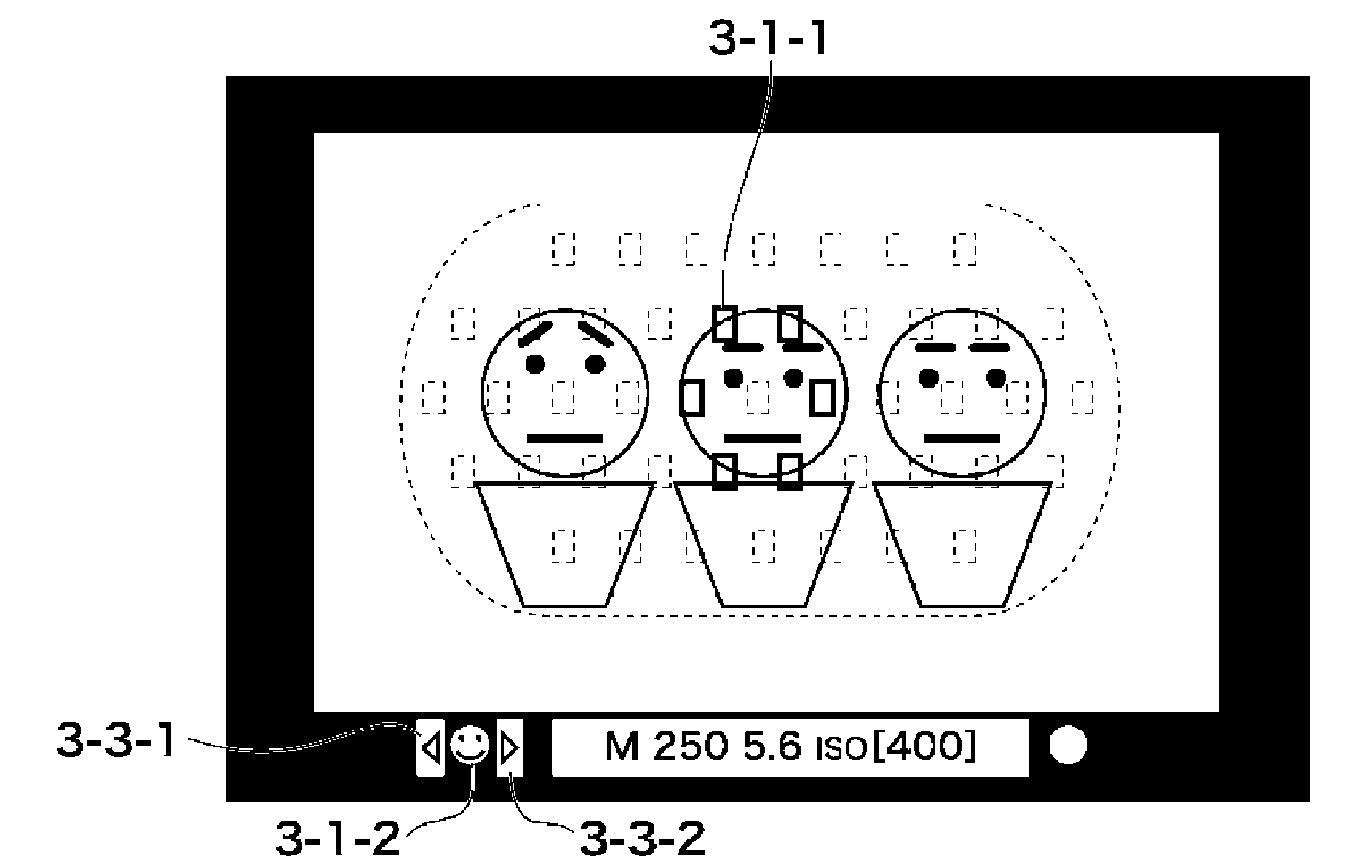
The present invention provides an image pick-up apparatus and a control method that can display a detected subject region in a field of view of an optical finder intelligibly and shorten the time until achieving a focus on a subject to decrease a release time lag. This is achieved by detecting data about focus adjustment of a subject, indicating a focusing point among multiple positions in the field of view, detecting a region of the subject using a different signal, and controlling the indication unit accordingly to surround the region of the subject. Overall, this invention improves the user experience and efficiency of image pick-up.

Problems solved by technology

Further, it decreases a frequency of losing a subject from the focusing points when shooting a moving subject.
Accordingly, for example in person photography, when another body such as a flower or a ball is located at the nearest position, there is a problem that the camera focuses on the other body and not on the person.
Therefore, such an AF operation needs a longer time until the camera focuses on a subject as compared with the case where the AF operation is performed using the focusing sensor, which causes a problem of increasing a release time lag.
However, since only one index (frame) is illuminated in this technique, there is a problem in which it is unclear whether the subject is caught as a region.

Method used


Image

  • Image pick-up apparatus and control method therefor
  • Image pick-up apparatus and control method therefor
  • Image pick-up apparatus and control method therefor

Examples


Embodiment Construction

[0033]Hereafter, embodiments according to the present invention will be described in detail with reference to the drawings.

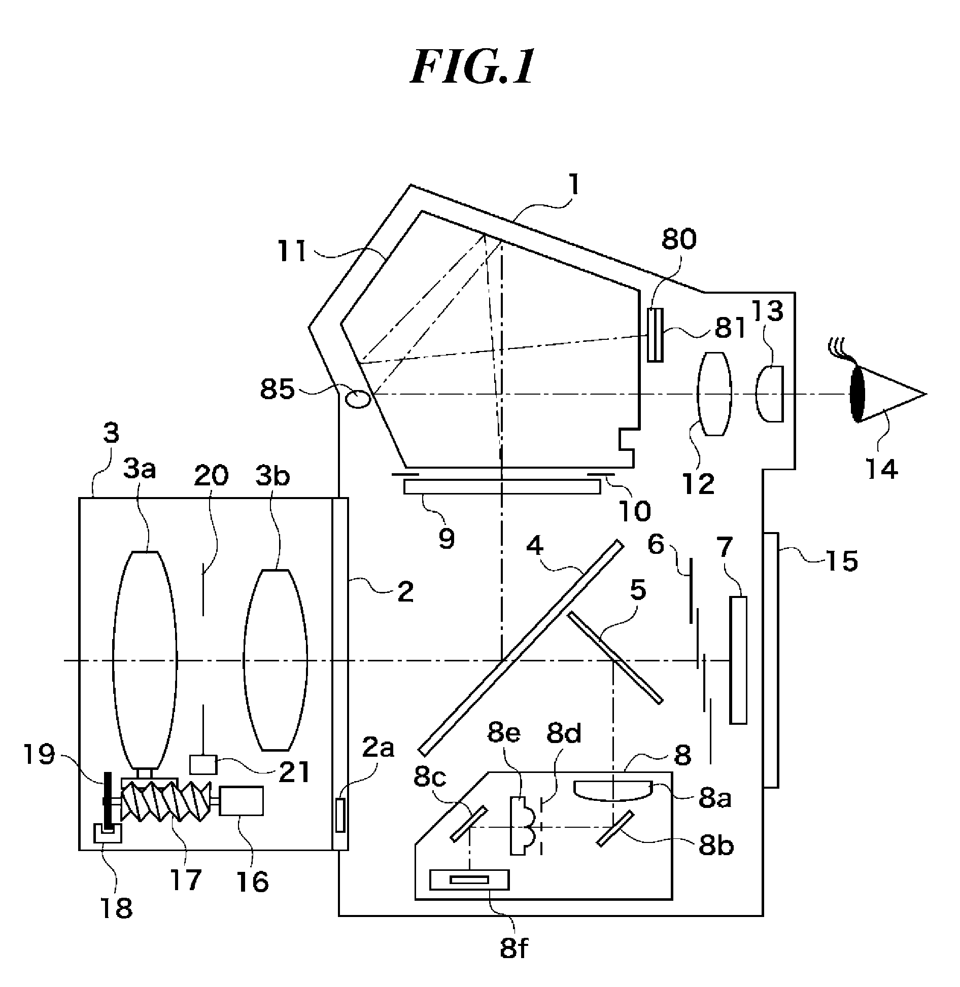
[0034]FIG. 1 is a schematic sectional view of a digital single lens reflex camera (referred to as “a camera”, hereinafter) that is an example of an embodiment of an image pick-up apparatus of the present invention.

[0035]In the camera of the present embodiment, as shown in FIG. 1, a mount 2 of a camera body 1 is equipped with a removable taking lens 3, for example. The mount 2 has mount contacts 2a as an interface for communicating various signals and supplying driving electric power.

[0036]A main mirror 4 that is constituted by a half mirror is arranged in the camera body 1 so as to rotate according to an operating condition of the camera. The main mirror 4 is diagonally arranged in a taking optical path for bending a light flux from the taking lens 3 to be guided to an optical finder system (described later) when observing a subject through the optical finder. A...


PUM


Abstract

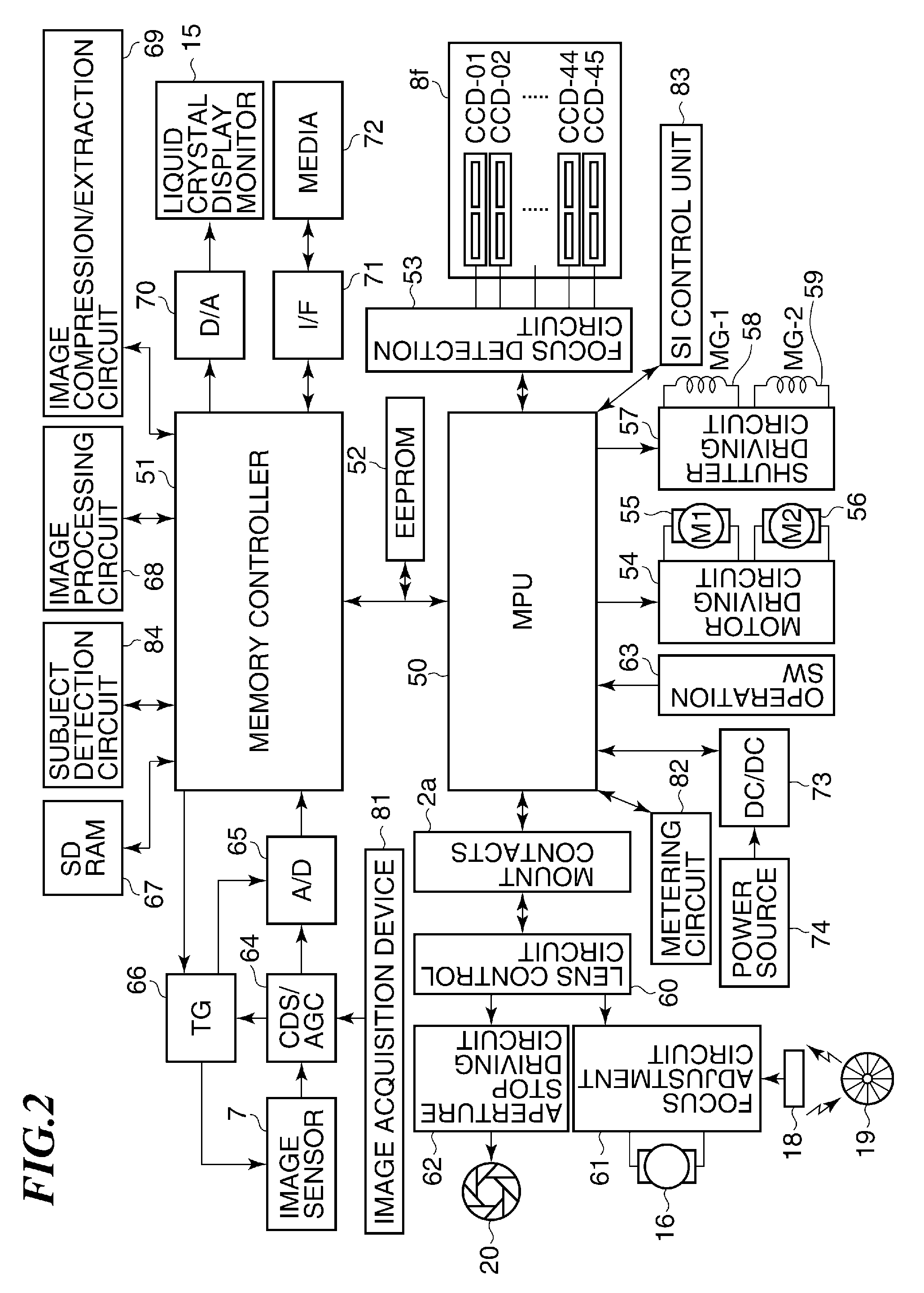
An image pick-up apparatus capable of displaying a detected subject region in a field of view of an optical finder intelligibly, and shortening a time until achieving a focus on a subject so as to decrease a release time lag. A focus detection unit detects data concerning a focus adjustment of a subject. An indication unit indicates a focusing point selected as a target of the focus adjustment among focusing points arranged at positions in a field of view of an optical finder according to the data detected by the focus detection unit. A subject detection unit detects a region of the subject using a signal that is different from the signal used for the detection in the focus detection unit. A control unit controls the indication unit based on the detection result of the subject detection unit so as to indicate the focusing points surrounding the region of the subject.

Description

BACKGROUND OF THE INVENTION[0001]1. Field of the Invention[0002]The present invention relates to an image pick-up apparatus such as a digital camera or a surveillance camera having an autofocus (AF) function, and to a control method for the image pick-up apparatus.[0003]2. Description of the Related Art[0004]A focus detection device in early stages of an image pick-up apparatus, such as a camera, was provided with one focusing point at the center of a taking area. The number of focusing points increased gradually according to development of a focus detection device, it progressed to three points, seven points, nine points, nineteen points, and reached forty-five points, which has broadened a possible area for focus detection within the taking area.[0005]Such an increase of the focusing points has the following advantages. That is, it can avoid so-called “out-of-focus in center” situation in which a camera focuses on a background and not on a subject in normal shooting. Further, it d...

Claims


Application Information

Patent Timeline
Patent Type & Authority Applications(United States)
IPC IPC(8): H04N5/228H04N23/40
CPCH04N5/23219H04N5/23212H04N23/675H04N23/61H04N23/611H04N23/635
Inventor SASAKI, FUTOSHI
Owner CANON KK
Learn More