
Image coding device and image decoding device

a coding device and image technology, applied in the field of image coding devices and image decoding devices, can solve the problems of significant increased influence of quantization error in the prediction image by the intra prediction to the decoded image, and significant deterioration of decoded image. to achieve the effect of reducing subjective deterioration of image quality

Inactive Publication Date: 2010-02-11
PANASONIC CORP
View PDF11 Cites 59 Cited by
  • Summary
  • Abstract
  • Description
  • Claims
  • Application Information

AI Technical Summary

Benefits of technology

[0022]With the above structure, the present invention can select an appropriate intra prediction mode for an outline of a face image even with a low bit-rate. As a result, it is possible to reduce subjective deterioration of image quality.

Problems solved by technology

When this MPEG-4 AVC is used in a network camera requiring a low bit-rate, influence of quantization error in the prediction image by the intra prediction to the decoded image is increased, because a bit amount which can be allocated to a difference image of each block is not enough at the low bit-rate.
In the above situation, if the selected intra prediction mode is not appropriate, the resulting decoded image is significantly deteriorated.
Especially deterioration occurring on an outline of an image of a face (hereinafter, referred to simply as a “face” of “face image”) is significant subjective deterioration of image quality.

Method used


Image

  • Image coding device and image decoding device
  • Image coding device and image decoding device
  • Image coding device and image decoding device

Examples


embodiment 1

[0062]FIG. 5 is a block diagram of an image coding device 800 according to Embodiment 1 of the present invention.

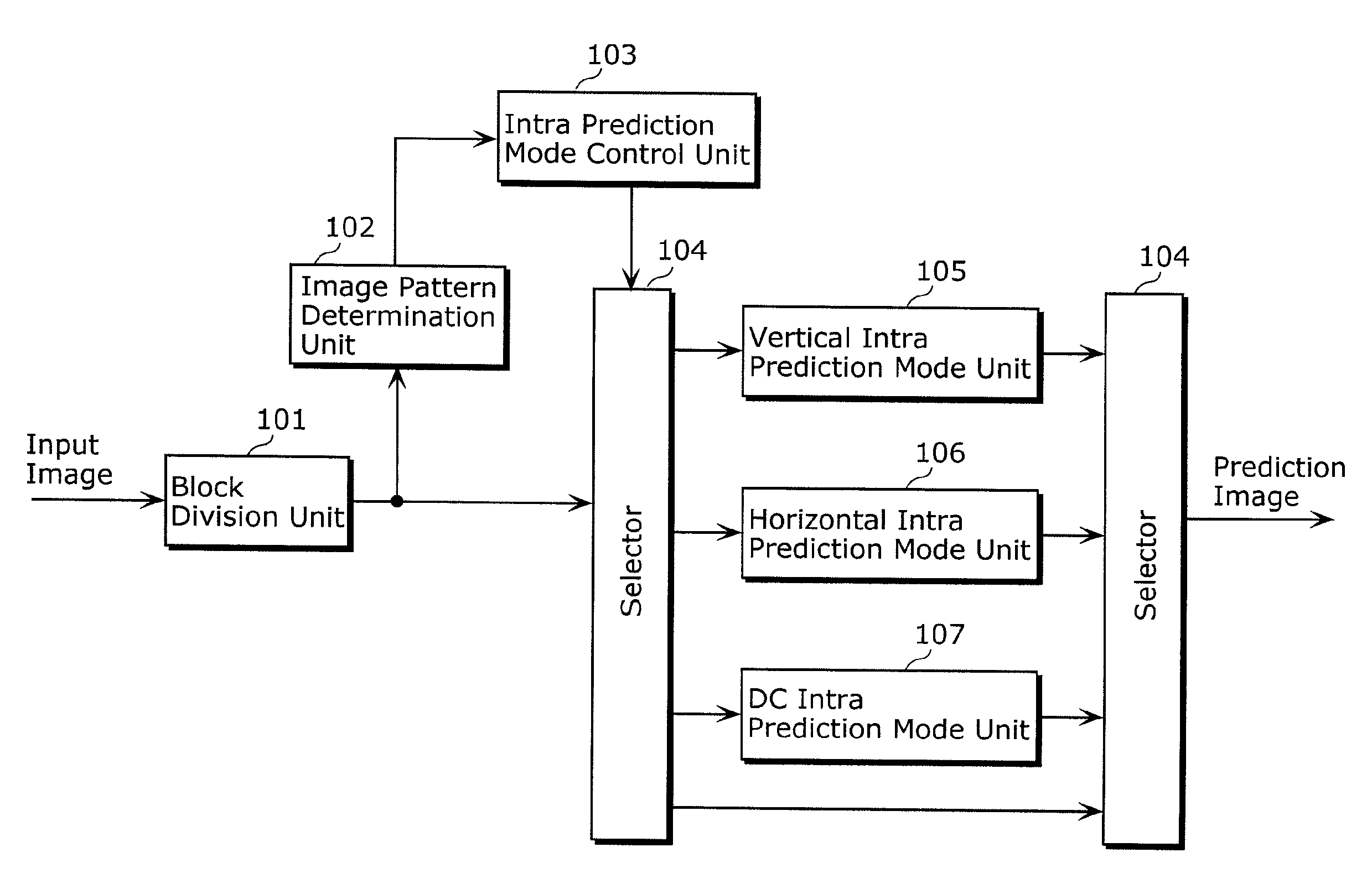
[0063]The image coding device 800 according to Embodiment 1 detects an outline of a face in an input picture and specifies a rectangular region including the face (hereinafter, referred to as a “face image region”). Then, the image coding device 800 selects a vertical intra prediction mode for a current block including a part of a vertical boundary of the specified face image region, and selects a horizontal intra prediction mode for a current block including a part of a horizontal boundary of the specified face image region. The image coding device 800 includes a block division unit 801, an orthogonal transformation unit 802, a quantization unit 803, an entropy coding unit 804, an inverse quantization unit 805, an inverse orthogonal transformation unit 806, a loop filter 807, a first picture memory 808, an intra prediction unit 809, a second picture memory 810, an inter ...

embodiment 2

[0081]FIG. 10 is a block diagram of an image decoding device 900 according to Embodiment 2 of the present invention. The image decoding device 900 specifies a face region in an decoded picture immediately prior to a currently-decoding picture (hereinafter, a “current picture”) in input pictures generated by decoding a coded stream. Face image region information indicating the specified face region is used for the current picture. If a current block in the current picture includes a part of a vertical boundary of the face region, intra prediction is performed on the current block at a vertical intra prediction mode. If a current block in the current picture includes a part of a horizontal boundary of the face region, intra prediction is performed on the current block at a horizontal intra prediction mode. Thereby, the image decoding device 900 generates an intra prediction image with less deterioration of image quality. Here, the image decoding device 900 does not consider an intra p...


PUM


Abstract

There is a problem of increasing image quality deterioration when selection of an intra prediction mode for a face outline portion is not correct at a low bit-rate. This invention includes: a face detection unit detecting a face image from an input picture; and an intra prediction mode control unit controlling intra prediction mode selection based on a result of the detection of the face detection unit. In the control of intra prediction mode selection, an intra prediction mode is selected based on where a current block is positioned in a region of the face image. Thereby, an appropriate intra prediction mode can be selected for the face outline portion. As a result, image quality deterioration on the face image at a low bit-rate can be prevented.

Description

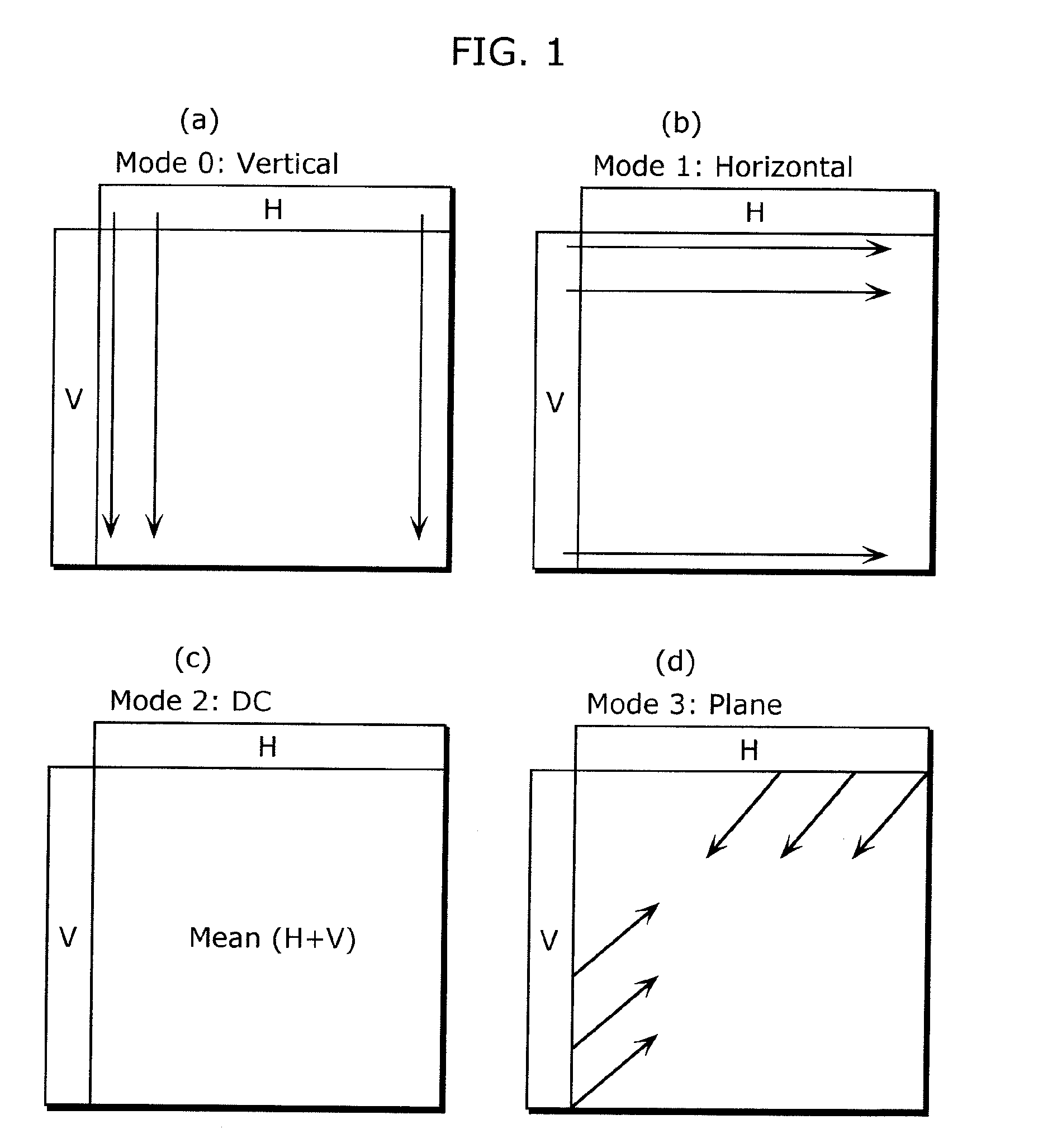
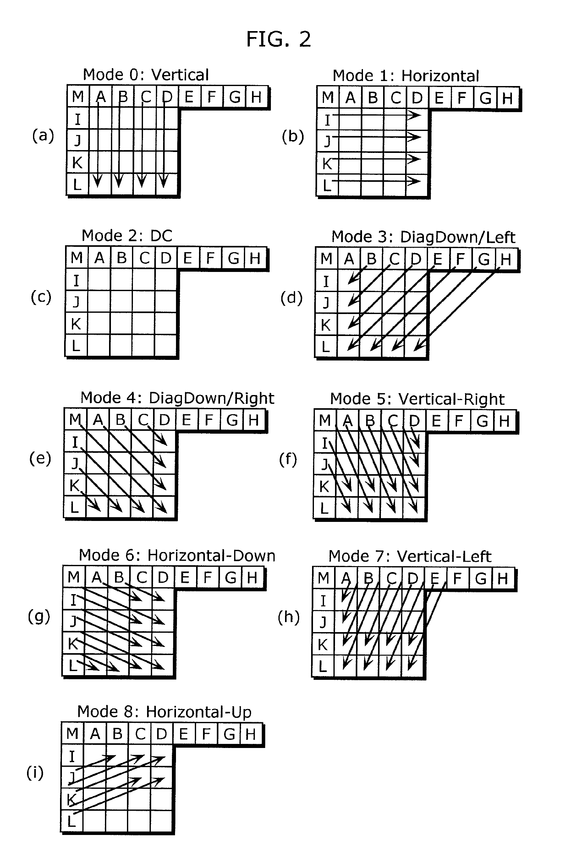
TECHNICAL FIELD[0001]The present invention relates to image coding devices and image decoding devices for detecting an image of a face from an input image and using a result of the detection in coding and decoding the input image.BACKGROUND ART[0002]There is a standard technology of coding video data, known as “MPEG-4 Part 10: Advanced Video Coding (MPEG-4 AVC)” established by Moving Picture Experts Group (MPEG) of Joint Technical Committee 1 of the International Organization for Standardization and the International Electrotechnical Commission (ISO / IEC JTC 1). This MPEG-4 AVC employs intra prediction by which prediction is performed using neighbor pixels in a target frame for intra-frame coding. In the intra-frame coding, prediction coding is performed with reference to only pixels in the same frame.[0003]The intra prediction of MPEG-4 AVC uses different modes for luminance components and chrominance components.[0004]For luminance components, intra prediction modes are classified i...

Claims


Application Information

Patent Timeline
IPC IPC(8): H04N7/50
CPCG06K9/00261H04N19/61H04N19/17H04N19/11H04N19/136H04N19/593G06V40/167
Inventor KUSAKABE, TOSHIHIKOINOUE, AKIHIKO
Owner PANASONIC CORP
Learn More