Side mounted drill bolt and threaded anchor system for veneer wall tie connection

a technology of threaded anchor system and drill bolt, which is applied in the direction of threaded fasteners, nuts, mechanical devices, etc., can solve the problems of affecting the continuity and integrity of wall boards and insulation, creating an oversized void in and requiring workmen to fashion cut-outs through wall sheets and insulation boards

Inactive Publication Date: 2010-02-18
BRONNER JOSEPH
View PDF67 Cites 78 Cited by
  • Summary
  • Abstract
  • Description
  • Claims
  • Application Information

AI Technical Summary

Benefits of technology

[0011]In accordance with one aspect of the present invention, a load transfer system includes a back-up wall and at least one panel disposed adjacent the back-up wall. A veneer wall is spaced from the back-up wall. A drill bolt having a generally cylindrical shaft extending between first and second ends is provided. A portion of the shaft adjacent the first end is secured to the back-up wall and a portion of the shaft adjacent the second end extends through a penetration hole in the at least one panel. A clip is disposed on the second end of the drill bolt within the space between the back-up wall and the veneer wall. A wire tie extends between the clip and the veneer wall.

Problems solved by technology

One major drawback of the above-noted prior art systems is that a worker must fashion a cut-out through wall sheeting and insulation boards, e.g., with a reciprocating saw, or position multiple panels together in order to make space for securing an anchor plate to a back up-wall.
The cut-out or spacing between multiple panels is typically larger than the dimensions of the anchor plate, thereby creating an oversized void in the wall sheeting and insulation boards.
Further, regardless of whether the anchor plate is secured to a back-up wall prior to installation of the wall sheeting or insulation boards or after, the anchor plate will still interfere with the continuity and the integrity of the wall boards and insulation.
Utilizing such prior art systems thus results in wasted material, requires the use of additional labor, money, and time, and achieves a less desirable installation.
Another disadvantage to the prior art systems is that the relatively large voids that are created to mount the anchor plate to the back-up wall must be sealed and the rigid panels, if present, must be supported.
Supporting the panels and sealing the conventional voids requires relatively large cover plates to be placed over the voids and the expenditure of a significant amount of labor and cost to install them.
Because the adjustability in the prior art system is very limited, there is no certainty that the seal plate will be tightly held against the rigid sheeting or board panels.

Method used


Image

  • Side mounted drill bolt and threaded anchor system for veneer wall tie connection
  • Side mounted drill bolt and threaded anchor system for veneer wall tie connection
  • Side mounted drill bolt and threaded anchor system for veneer wall tie connection

Examples


Embodiment Construction

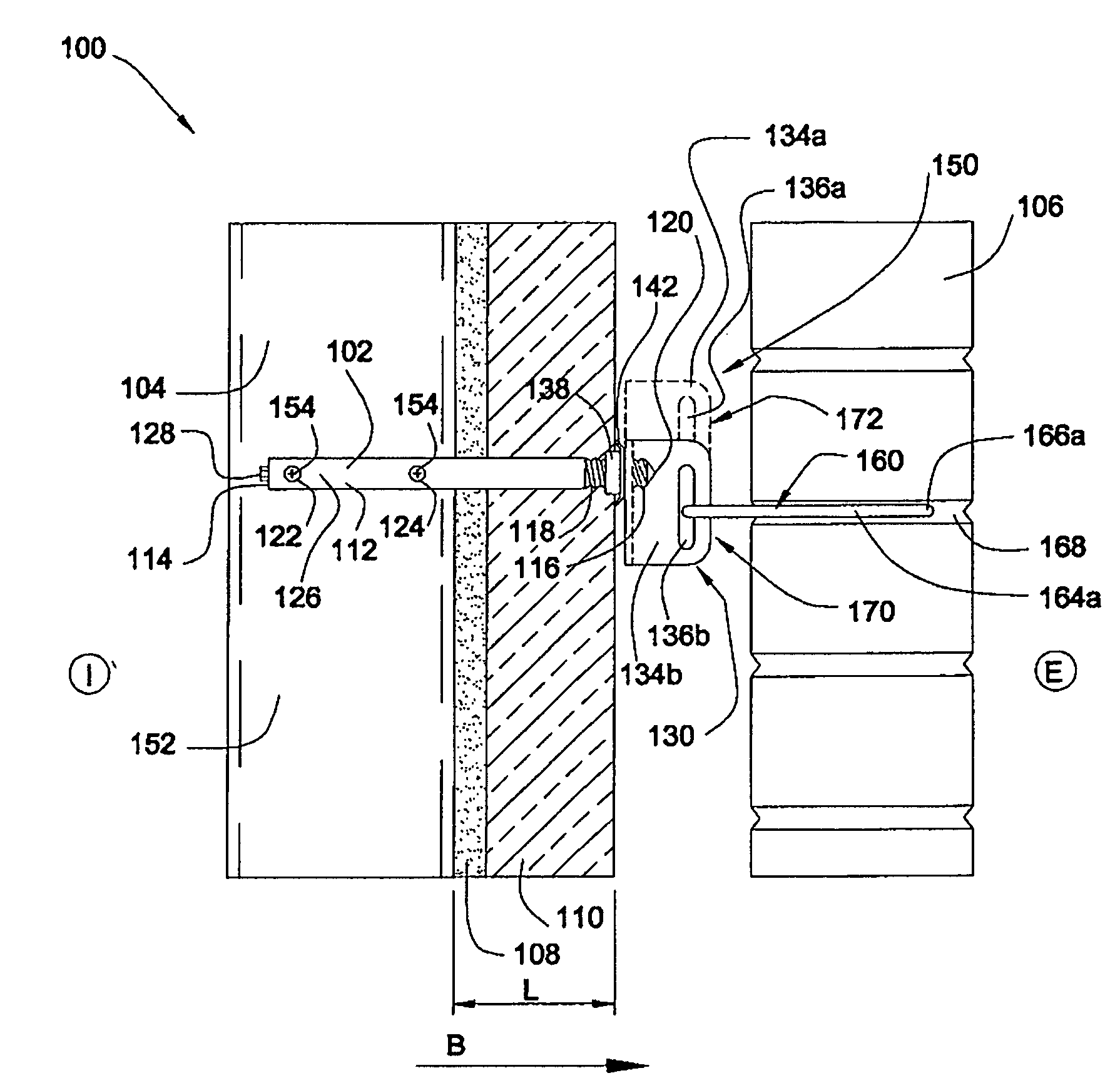
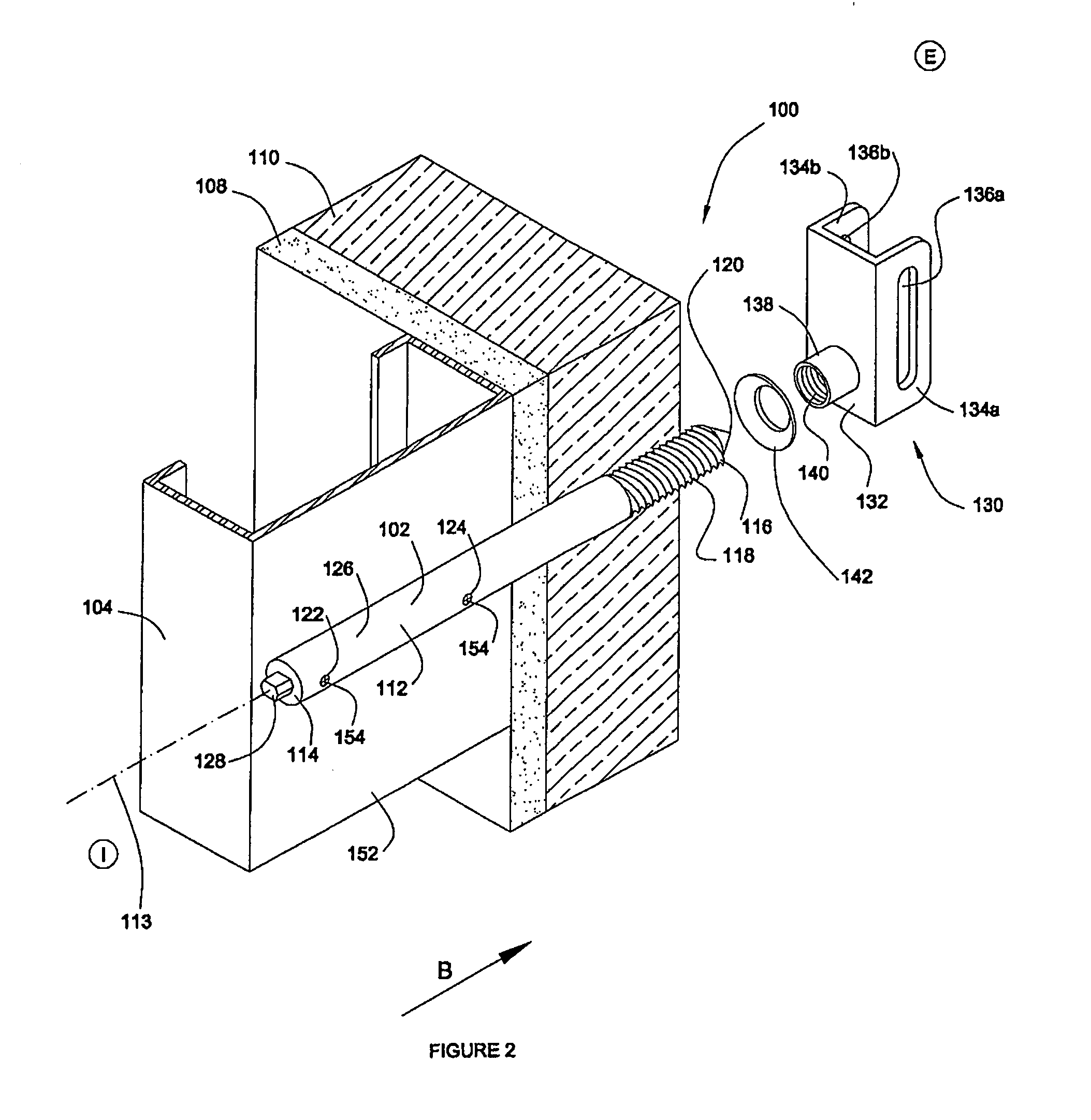
[0048]Turning now to FIGS. 2-6 and 8, one embodiment of a load transfer system 100 is depicted. The load transfer system 100 generally includes a drill bolt 102, a back-up wall 104, and a veneer wall 106. The back-up wall 104 may comprise any number of structures known to those of skill in the art, including stud walls, wood stud walls, masonry walls, concrete walls with steel elements, etc. In many cases the structural elements of the back-up wall are overlaid with panels such as wall sheeting and / or insulation boards. For purposes of the embodiments discussed herein, it will be assumed that the back-up wall 104 comprises vertical steel studs, which are overlaid by gypsum board sheeting 108 (or wall sheeting 108) and rigid insulation boards 110 (or insulation 110). Similarly, the veneer wall 106 may comprise any type of veneer known to those of skill in the art, including brick veneer, stone veneer, masonry veneer, stucco, etc. However, for purposes of the embodiments discussed her...


PUM


Abstract

In accordance with one aspect of the present invention, a load transfer system includes a back-up wall and at least one panel disposed adjacent the back-up wall. A veneer wall is spaced from the back-up wall. A drill bolt having a generally cylindrical shaft extending between first and second ends is provided. A portion of the shaft adjacent the first end is secured to the back-up wall and a portion of the shaft adjacent the second end extends through a penetration hole in the at least one panel. A clip is disposed on the second end of the drill bolt within the space between the back-up wall and the veneer wall. A wire tie extends between the clip and the veneer wall.

Description

CROSS-REFERENCE TO RELATED APPLICATIONS[0001]This application claims the benefit of U.S. Provisional Application Ser. No. 61 / 188,826, filed Aug. 13, 2008, and incorporated herein by reference in its entirety.SEQUENTIAL LISTING[0002]Not applicableBACKGROUND OF THE INVENTION[0003]1. Field of the Invention[0004]The present disclosure relates generally to a side-mounted system for transferring horizontal loads between a back-up wall and a veneer wall, and more particularly, to connecting an anchor shaft extending from the back-up wall or other building support to a wire tie extending from the veneer wall.[0005]2. Description of the Background of the Invention[0006]Much of today's building construction consists of masonry veneer wall supported for horizontal transverse loads by a structural back-up wall. The back-up wall can consist of stud wall, masonry wall, concrete wall with steel elements, or any other material known to those of skill in the art. The back-up wall supports the veneer...

Claims


Application Information

Patent Timeline
Patent Type & Authority Applications(United States)
IPC IPC(8): E04B1/38E04B1/41
CPCE04B1/4178F16B45/00F16B37/00
Inventor BRONNER, JOSEPH
Owner BRONNER JOSEPH
Why Eureka
Try Eureka