Laminated band-pass filter

a technology filter body, which is applied in the direction of waveguide type devices, resonators, electrical equipment, etc., can solve the problems of large insertion loss of laminated band-pass filter, increase in the q value of the inductor, and large magnetic coupling between the lc parallel resonators, etc., to achieve stable passband characteristics and sharp attenuation

Active Publication Date: 2010-02-18
MURATA MFG CO LTD
View PDF8 Cites 13 Cited by
  • Summary
  • Abstract
  • Description
  • Claims
  • Application Information

AI Technical Summary

Benefits of technology

[0014]In view of the above problems, preferred embodiments of the present invention provide a small-sized and low-loss laminate...

Problems solved by technology

For the laminated band-pass filter of Japanese Unexamined Patent Application Publication No. 4-6911, the inductor included in each of the LC parallel resonators is made up of a two-layer inductor pattern, so a problem arises in which magnetic coupling between the LC parallel resonators is large.
The inductor made up of the two-layer inductor pattern causes a problem in which a decrease in the Q value of the inductor increases the insertion loss of the laminated band-pass filter.
This results in a problem in which the thickness of the laminated band-pass filte...

Method used


Image

  • Laminated band-pass filter
  • Laminated band-pass filter
  • Laminated band-pass filter

Examples


first preferred embodiment

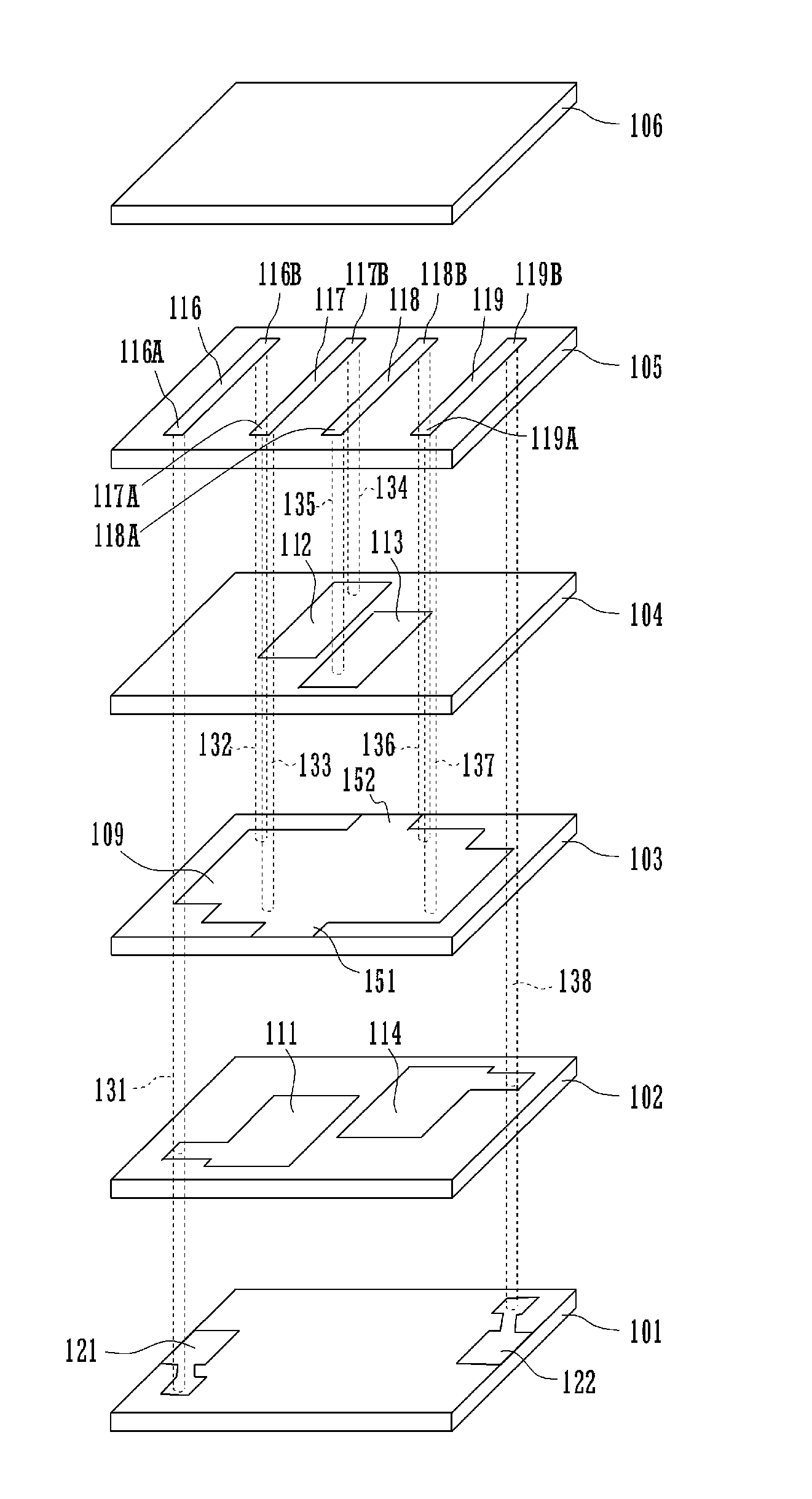
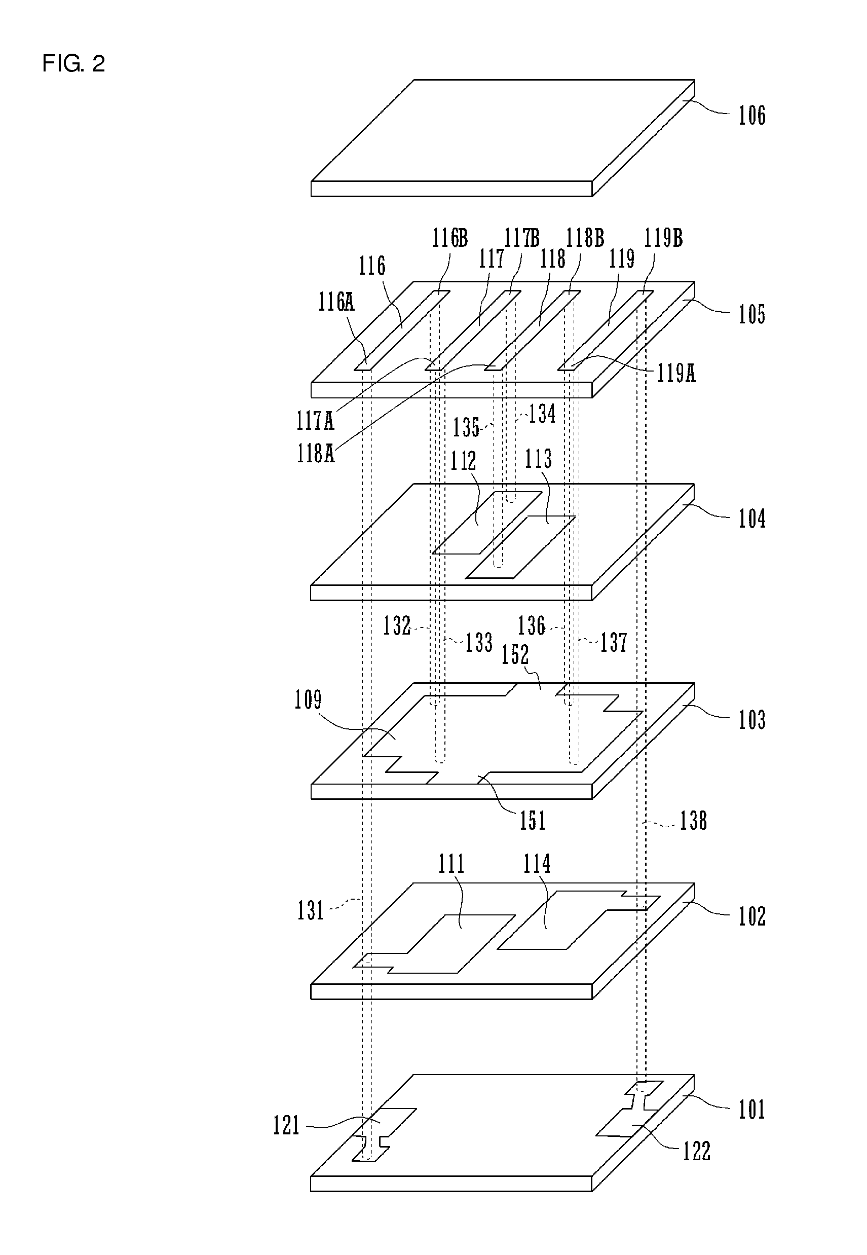
[0040]A laminated band-pass filter according to a first preferred embodiment is described with reference to FIGS. 2-5.

[0041]FIG. 2 is an exploded perspective view of a laminated band-pass filter according to the first preferred embodiment, and FIG. 3 is an external perspective view thereof.

[0042]In FIG. 2, a ground electrode 109 is disposed on the upper surface of a ground electrode formation layer 103. Capacitor electrodes111 and 114 are disposed in a capacitor electrode formation layer 102. Capacitor electrodes 112 and 113 are disposed in a capacitor electrode formation layer 104. Input / output electrodes 121 and 122 are disposed in an input / output electrode formation layer 101. Line electrodes 116 to 119 are disposed in a line electrode formation layer 105. An external layer 106 is disposed above the line electrode formation layer 105. The laminated band-pass filter has a laminated structure preferably including six dielectric layers and five electrode layers and having terminal e...

second preferred embodiment

[0077]A laminated band-pass filter according to a second preferred embodiment is described with reference to FIGS. 6 and 7. FIG. 6 is an exploded perspective view of the laminated band-pass filter according to the second preferred embodiment.

[0078]In FIG. 6, a ground electrode 209 is disposed on the upper surface of a ground electrode formation layer 201. Capacitor electrodes 211, 212, 213, and 214 are disposed in a capacitor electrode formation layer 202. Input / output electrodes 221 and 222 are disposed in an input / output electrode formation layer 203. Line electrodes 216 to 219 are disposed in a line electrode formation layer 204. An external layer 205 is disposed above the line electrode formation layer 204. The laminated band-pass filter defines a laminated structure preferably including five dielectric layers and four electrode layers and having terminal electrodes disposed on end surfaces.

[0079]The material of the dielectric layer portion of each layer is substantially the sam...


PUM


Abstract

In a laminated band-pass filter, a capacitance is formed between a ground electrode of a ground electrode formation layer and each of capacitor electrodes of capacitor electrode formation layers. An even number of LC parallel resonators is arranged such that via electrodes and line electrodes define a plurality of inductor electrodes and, when viewed in a direction in which the inductor electrodes are arranged, the surfaces of the loops of the inductor electrodes overlap each other at least partially. The loops defined by the inductor electrodes of neighboring LC parallel resonators have opposite directions. The capacitor electrodes have a shape and distribution or arrangement having point symmetry in plan view.

Description

BACKGROUND OF THE INVENTION[0001]1. Field of the Invention[0002]The present invention relates to a laminated band-pass filter in which a plurality of dielectric layers and electrode layers are laminated.[0003]2. Description of the Related Art[0004]A traditional high-frequency band-pass filter suited for reducing its size and cost is one in which a plurality of LC resonators is disposed in a laminated structure of dielectric layers and electrode layers. Examples of such a laminated band-pass filter are disclosed in Japanese Unexamined Patent Application Publication No. 4-6911, Japanese Unexamined Patent Application Publication No. 2000-201001, Japanese Unexamined Patent Application Publication No. 2003-198226, and International Publication No. WO 02 / 009225[0005]The configuration of the laminated band-pass filter in Japanese Unexamined Patent Application Publication No. 4-6911 is described with reference to FIGS. 1A and 1B. FIG. 1A is a circuit diagram thereof, and FIG. 1B is a cross-...

Claims


Application Information

Patent Timeline
IPC IPC(8): H03H7/01
CPCH01P1/20345H03H7/09H03H2001/0085H03H7/1775H03H7/1708H01P1/203H01P1/205H01P7/08
Inventor TANIGUCHI, TETSUO
Owner MURATA MFG CO LTD
Why Eureka
Try Eureka