
Elapsed Time Device

a display device and liquid crystal technology, applied in electromechanical unknown time interval measurement, instruments, horology, etc., can solve the problems of reducing the number of devices, reducing the accuracy of the measurement, so as to achieve the effect of not calling attention

Active Publication Date: 2010-02-18
ROGERS JANICE L
View PDF17 Cites 4 Cited by
  • Summary
  • Abstract
  • Description
  • Claims
  • Application Information

AI Technical Summary

Benefits of technology

[0012]The watch format of this elapsed time display is particularly advantageous to satisfy the needs of individuals with “special needs” who require “assistive technology” which is both portable and discrete. The invention of this application provides a solution to both of these needs in that, as a watch, it may be worn rather than carried, and has a look of a typical watch, so as not to call attention to the user.

Problems solved by technology

That mechanical device disclosed in U.S. Pat. No. 5,662,479 has numerous limitations because of its mechanical configuration.
Among those limitations is one of size, as well as portability and convenience in use.
Other limitations are time limitations in that that mechanical device is not amenable to time settings of more than one hour.

Method used


Image

  • Elapsed Time Device
  • Elapsed Time Device
  • Elapsed Time Device

Examples


Embodiment Construction

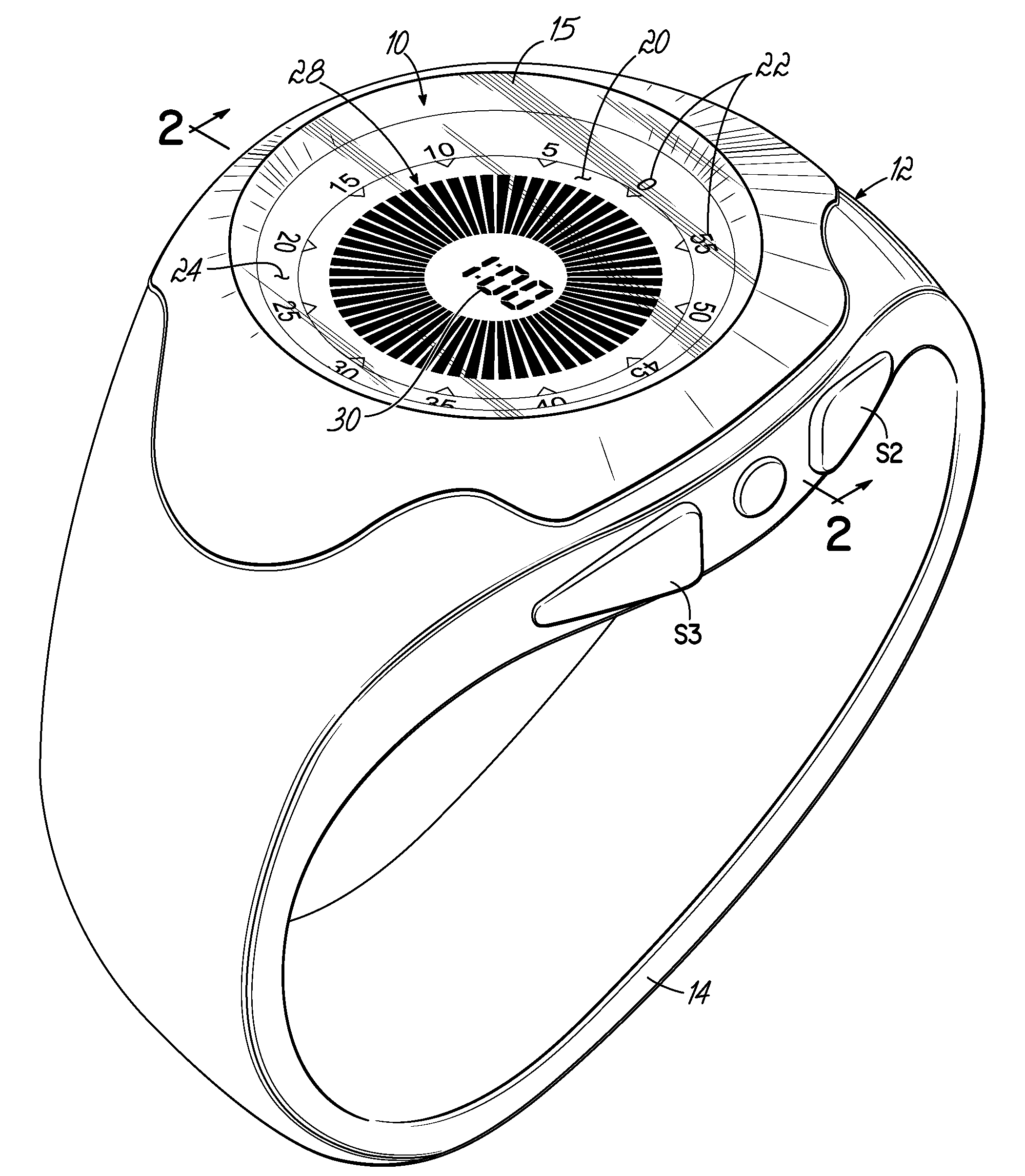
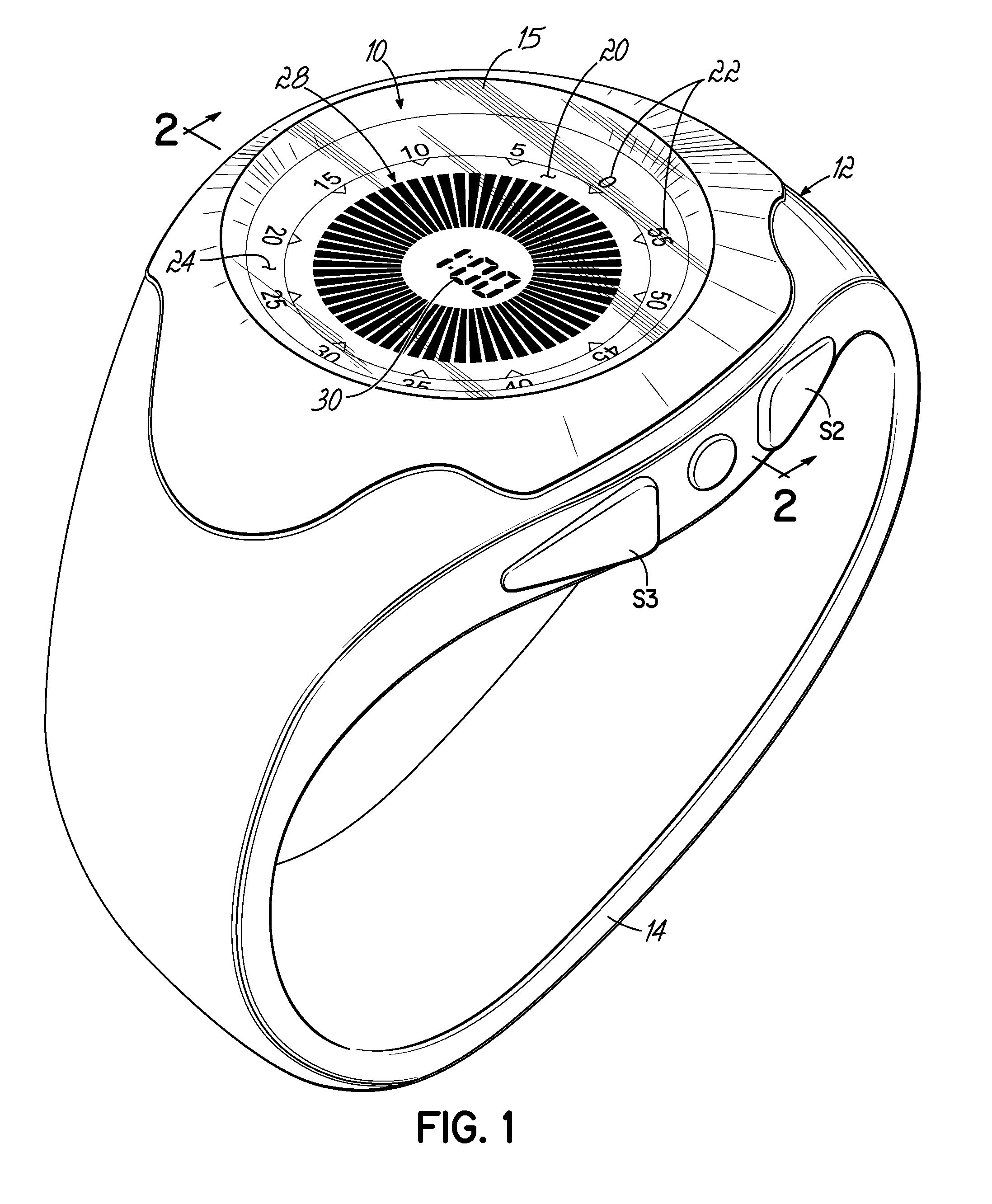
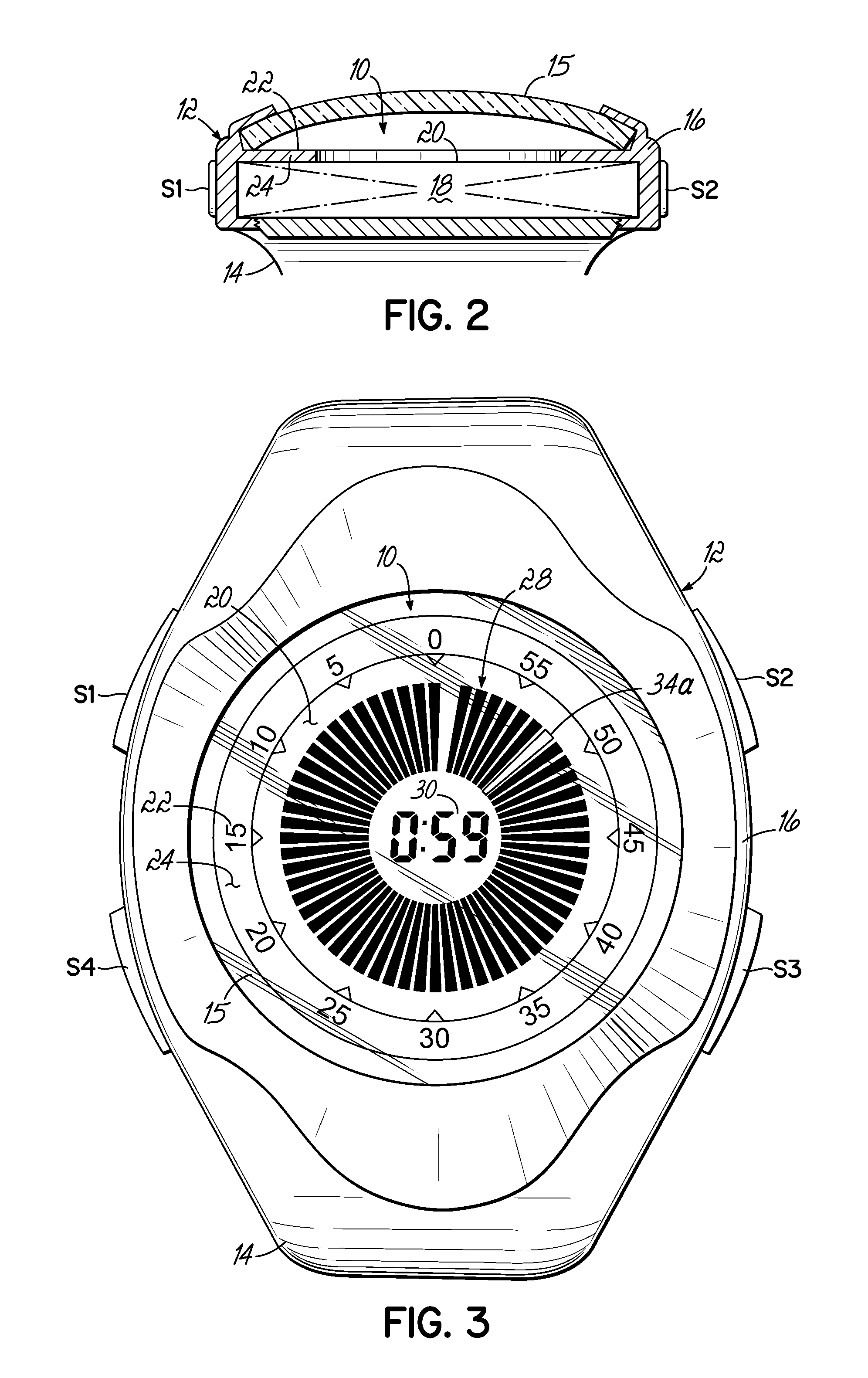
[0021]The elapsed time and remaining time liquid crystal display device 10 of this invention is illustrated in the drawings as embodied in a wrist watch, but it could just as well be applied to and incorporated in a free standing display device. In accordance with the practice of the illustrated embodiment of the invention, the device 10 is contained within a watch case 12 which is, in turn, encased within a molded wrist watch band 14. The band 14 is molded around the case 12 and includes four control or actuating buttons, S1, S2, S3 and S4. As explained more fully hereinafter, these buttons S1, S2, S3 and S4 actuate switches contained internally of the case 12 which, in turn, control setting and actuation of the mechanism contained within the case 12 of the device.

[0022]With reference to the cross sectional view of FIG. 2, it will be seen that the device 10 includes an external housing or body 16 internally of which there is located a liquid crystal display mechanism 18. A lens 15 ...


PUM


Abstract

An elapsed time and remaining time liquid crystal measuring device having a display face around the periphery of which there are a plurality of numerical indicia marks arranged in a generally clockwise pattern with successive numerical indicia marks decreasing in numerical value in a clockwise direction from a twelve o'clock position. An annular ring of electronically generated graphic indicia are visible on the display face and spaced inwardly from the peripheral numerical indicia and a digital numerical read-out display of elapsed times is visible internally of the annular ring of graphic indicia. There is at least one electronic control element for setting a desired elapsed set time into the device, which desired elapsed set time is indicated both on the digital read-out display and as a complete ring or an arcuate section of the annular ring on the display face. There is also an actuator for initiating progressive clockwise disappearing movement of the electronically generated graphic indicia so as to expose decreasing areas of the annular ring in a clockwise direction as time elapses and while the digital numerical display remains synchronized with the graphic indicia until all of the set time has elapsed. Preferably, the device is in the form of a wrist watch.

Description

CROSS REFERENCE TO RELATED APPLICATIONS[0001]This application is a continuation of U.S. patent application Ser. No. 11 / 875,408, filed Oct. 19, 2007, entitled “Elapsed Time Device”. U.S. patent application Ser. No. 11 / 875,408 claims the benefit of the filing of U.S. provisional Patent Application Ser. No. 60 / 852,739, filed Oct. 19, 2006, entitled “Time Timer Wrist Timer and Watch Plus”. Both of these applications are fully incorporated by reference herein.FIELD OF THE INVENTION[0002]This invention relates to a liquid crystal elapsed time display device and, more particularly, to such a device which displays remaining elapsed time in a graphic form on the face of the device. In one preferred embodiment, the device also is operative to display the time of day as well as elapsed time in alternative modes of operation of the device. Preferably, the device is in the form of a liquid crystal display wrist watch.BACKGROUND OF THE INVENTION[0003]In an earlier patent, U.S. Pat. No. 5,662,479,...

Claims


Application Information

Patent Timeline
Patent Type & Authority Applications(United States)
IPC IPC(8): G04C19/02G04C17/00
CPCG04F1/005G04G9/02G04F10/00
Inventor ROGERS, JANICE L.
Owner ROGERS JANICE L
Learn More