Rail arranged on a frame and provides multiple steps sliding movement

a technology of sliding movement and rails, which is applied in the field of rails, can solve the problems that the basic drawable function of a normal drawer provided to users in the beginning is not adaptable to a larger machine casing in the industry, and achieves the effect of improving the convenience of us

Inactive Publication Date: 2010-02-18
JUANG JHENG HONG
View PDF8 Cites 13 Cited by
  • Summary
  • Abstract
  • Description
  • Claims
  • Application Information

AI Technical Summary

Benefits of technology

[0007]Accordingly, the primary object of the present invention is to provide a multiple steps rail structure, and by a dip switch and a double-side stopping unit formed on a first sliding unit to improve the convenience of usage.

Problems solved by technology

A prior art of simple drawable function as a normal drawer provided to users in the beginning is not adaptable to a larger machine casing in industry.

Method used


Image

  • Rail arranged on a frame and provides multiple steps sliding movement
  • Rail arranged on a frame and provides multiple steps sliding movement
  • Rail arranged on a frame and provides multiple steps sliding movement

Examples


Embodiment Construction

[0020]In order that those skilled in the art can further understand the present invention, a description will be provided in the following in details. However, these descriptions and the appended drawings are only used to cause those skilled in the art to understand the objects, features, and characteristics of the present invention, but not to be used to confine the scope and spirit of the present invention defined in the appended claims.

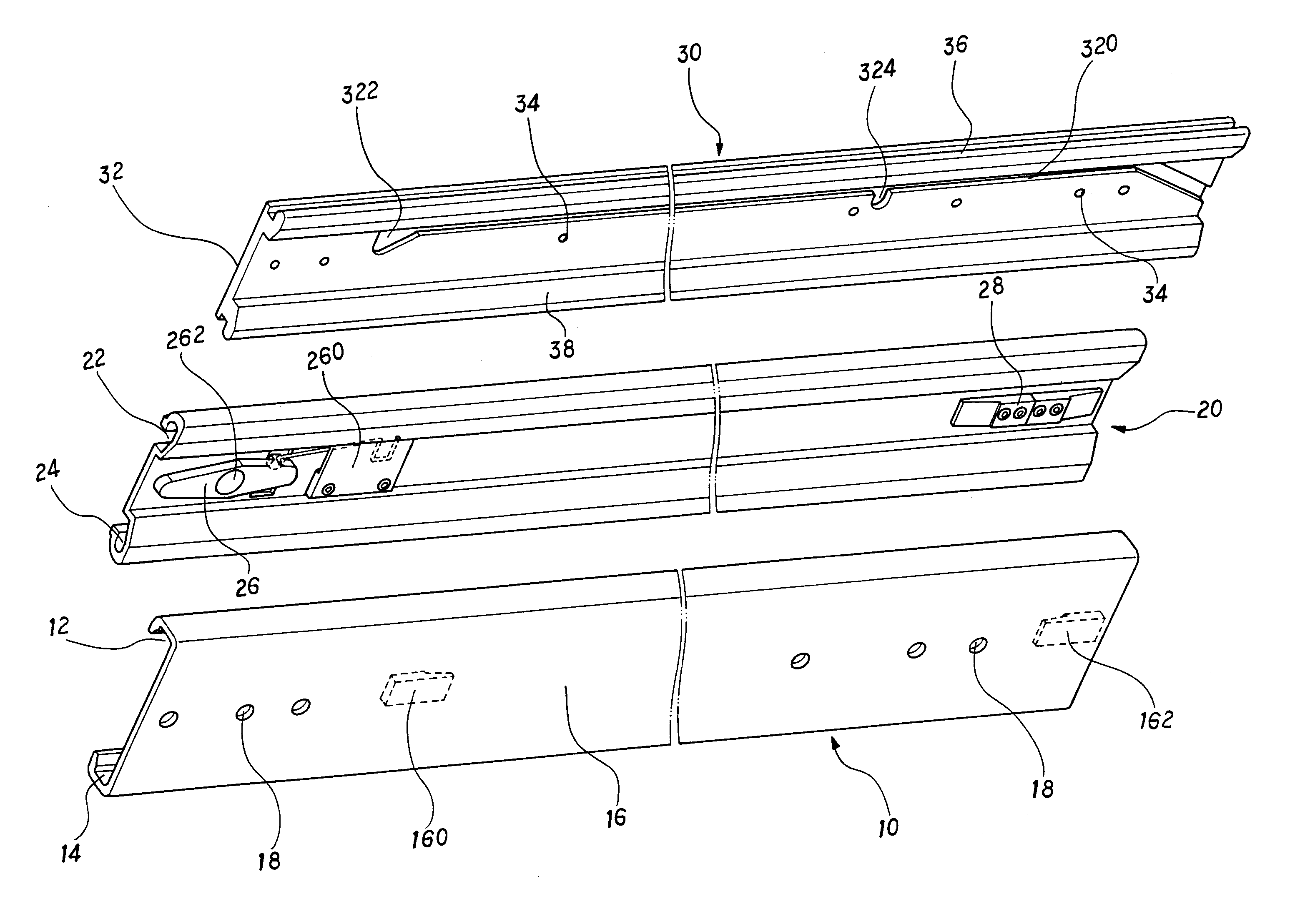
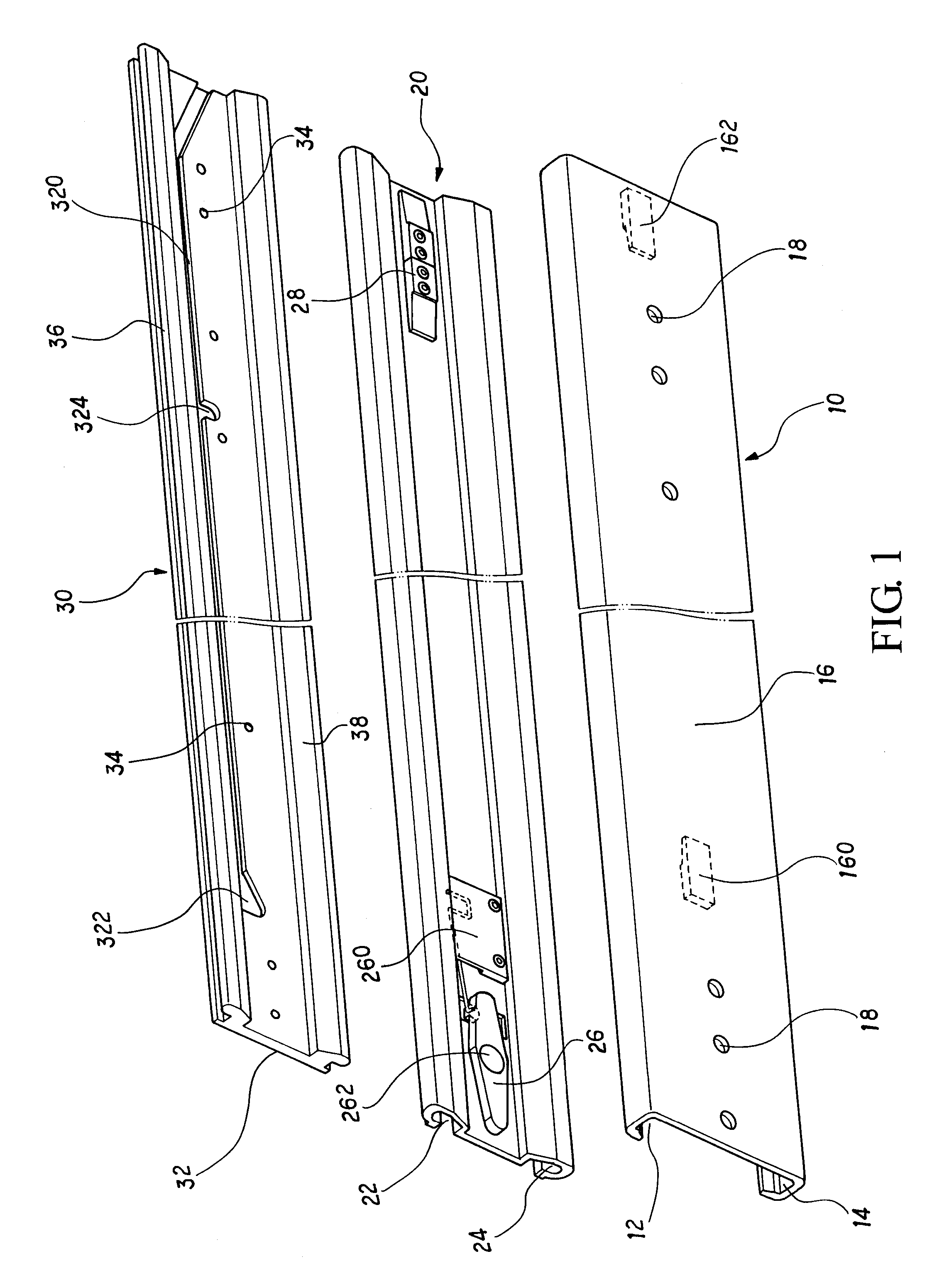
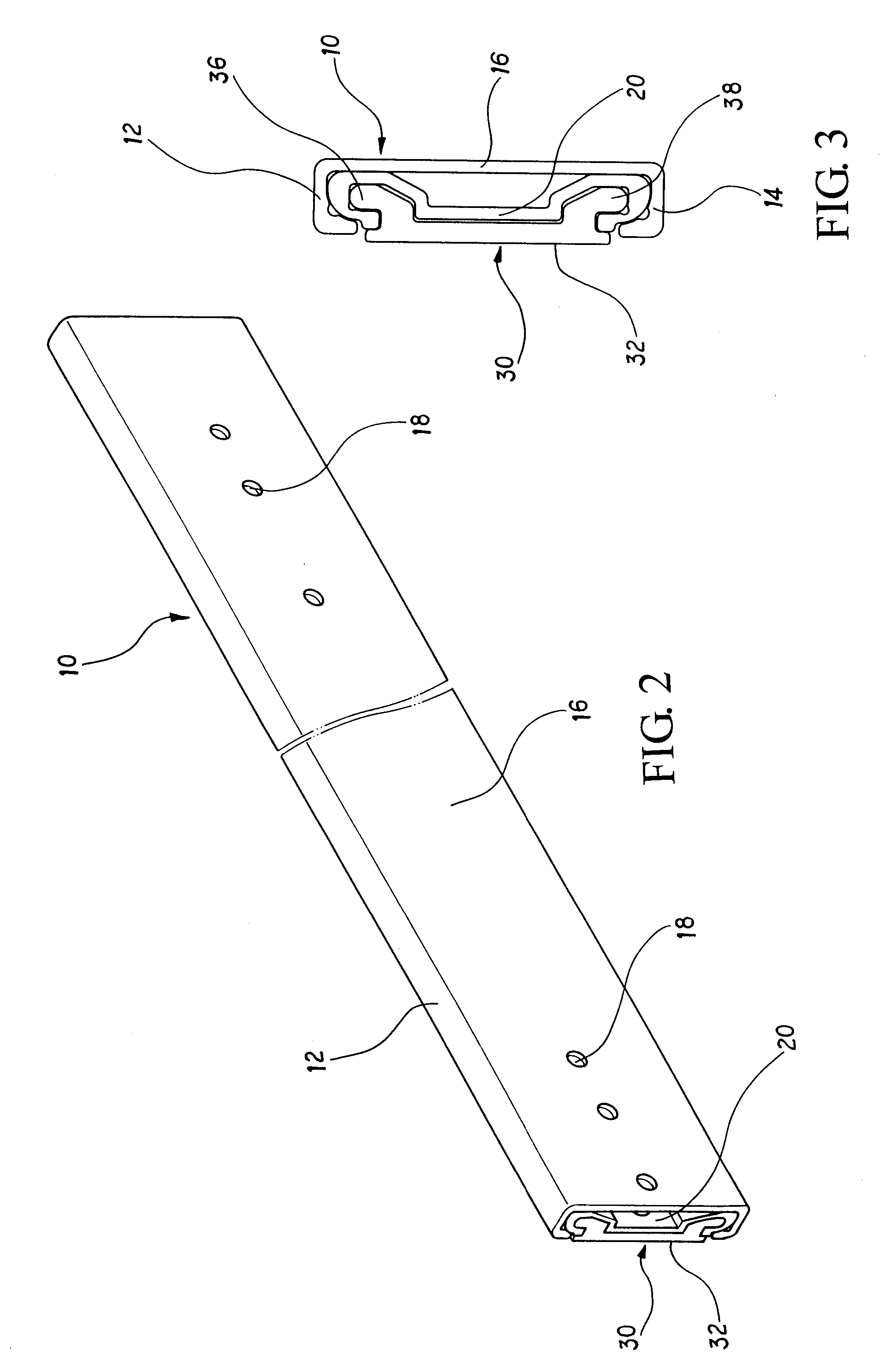
[0021]With reference of FIG. 1, the present invention includes a retainer 10 which each longitudinal side thereof is bent as a rectangular slot 12 and 14 respectively, and the retainer 10 is formed as an approximately concave body with a width d between the two slots. On a flat 16 of the retainer 10, a plurality of through holes 18 are formed so that the retainer 10 can be fixed on a frame 40 by a plurality of locking units as shown in FIG. 4. There are stopping units 160, 162 formed on the concave side of the retainer 10 on the flat 16. The stoppi...


PUM


Abstract

A multiple steps rail arranged in the two opposite sides of a frame includes a retainer, a first sliding unit, and a second sliding unit in each side. The retainer is approximately a concave body and a plurality of stopping units are formed on proper positions thereof. The first sliding unit is approximately a bow body and can be sliding arranged into the retainer. The first sliding unit further has a dip switch and a double-side stopping unit on a side facing the retainer. The second sliding unit is sliding arranged into the first sliding unit and can be fixed to a case body with a side thereof. When the case body is drawing out, the second sliding unit will slide out from the first sliding unit and the first sliding unit will slide out from the retainer in order.

Description

FIELD OF THE PRESENT INVENTION[0001]The present invention relates to a rail, and in particular to a rail arranged on a frame and provides multiple steps sliding movement.DESCRIPTION OF THE PRIOR ART[0002]A lot of designs of sliding guide and rail set are provided in the market nowadays. A prior art of simple drawable function as a normal drawer provided to users in the beginning is not adaptable to a larger machine casing in industry. Therefore, various designs with special functions are developed.[0003]For example, in one prior art relates to a positioning structure of a sliding unit of a drawer rail. It includes a positioning unit, a sliding unit, and a releasing unit. The positioning unit is arranged on an opening end of a first rail and a spring hook is extending from thereof. The sliding unit is arranged between the first rail and a second rail, and a front end thereof is formed as a slot. The releasing unit is installed to the first rail.[0004]When the second rail leaves the f...

Claims


Application Information

Patent Timeline
Patent Type & Authority Applications(United States)
IPC IPC(8): A47B88/08A47B88/49
CPCA47B2210/007A47B88/08A47B88/49
Inventor JUANG, JHENG-HONG
Owner JUANG JHENG HONG
Why Eureka
Try Eureka