Low-noise pneumatic tire

a pneumatic tire and low-noise technology, applied in the direction of tyres, vehicle components, without separate inflatable inserts, etc., can solve the problems of tire noise, repeated deformation of partition plates, air inside the tires to resonate, etc., and achieve the effect of further reducing the noise in the vehicle compartmen

Inactive Publication Date: 2010-02-25
YOKOHAMA RUBBER CO LTD
View PDF0 Cites 26 Cited by
  • Summary
  • Abstract
  • Description
  • Claims
  • Application Information

AI Technical Summary

Benefits of technology

[0015]In the low-noise pneumatic tire of the present invention, the multiple types of convex portions differing from each other in protruding height are formed on at least the region of the inner wall surface of the inner liner layer, the region corresponding to the tread portion. Each of the convex portions has a strip shape, protrudes from the inner liner layer, and extends in the tire width direction. The convex portions are intermittently arranged in the tire circumferential direction. Accordingly, the multiple types of convex portions differing from each other in protruding height efficiently diffuse resonance sounds generated in a tire cavity portion, and the resonance sounds cancel each other out because of the diffuse reflection. Thus, a noise in the vehicle compartment is further reduced.

Problems solved by technology

One of the causes of tire noise is a cavity resonance sound that occurs due to vibration of air filled inside the tire.
When the tire rolls under load, a tread portion that comes into contact with a road surface is vibrated by the roughness of the road surface, and this vibration causes the air inside the tire to resonate.
However, when such a rubber-made partition plate is provided to the inner portion of a cured tire, the partition plate is repeatedly deformed by rolling of the tire and detached from the tire inner portion after an extended period of use.
For this reason, this technique has a durability problem and also has a problem that the noise-reducing effect is difficult to maintain over an extended period.

Method used


Image

  • Low-noise pneumatic tire
  • Low-noise pneumatic tire
  • Low-noise pneumatic tire

Examples


examples

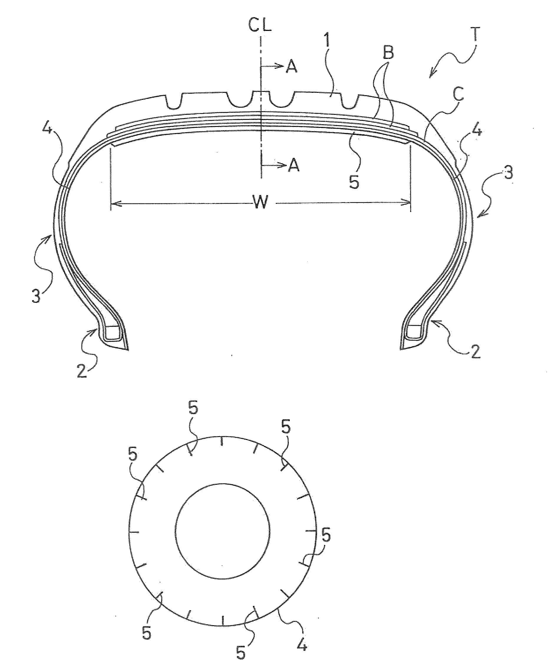
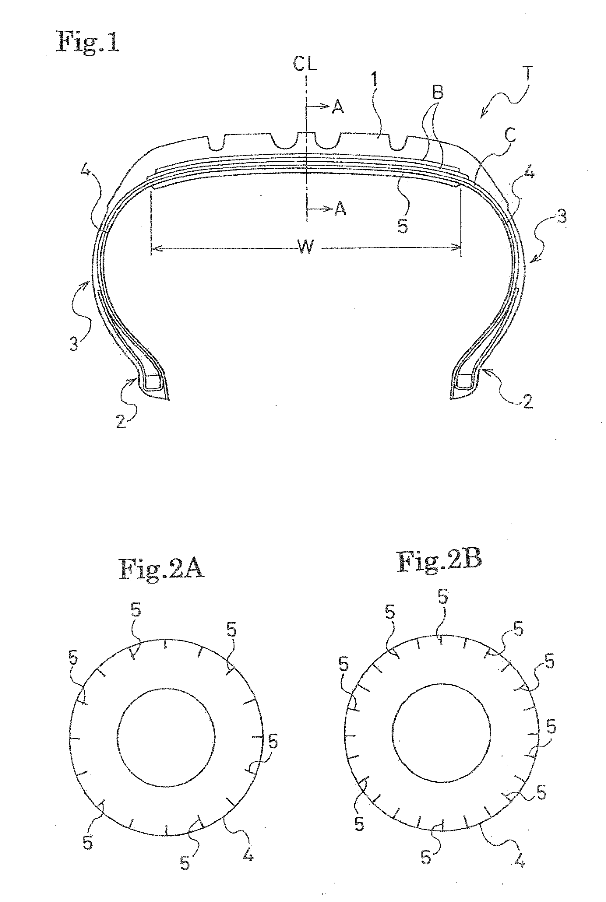
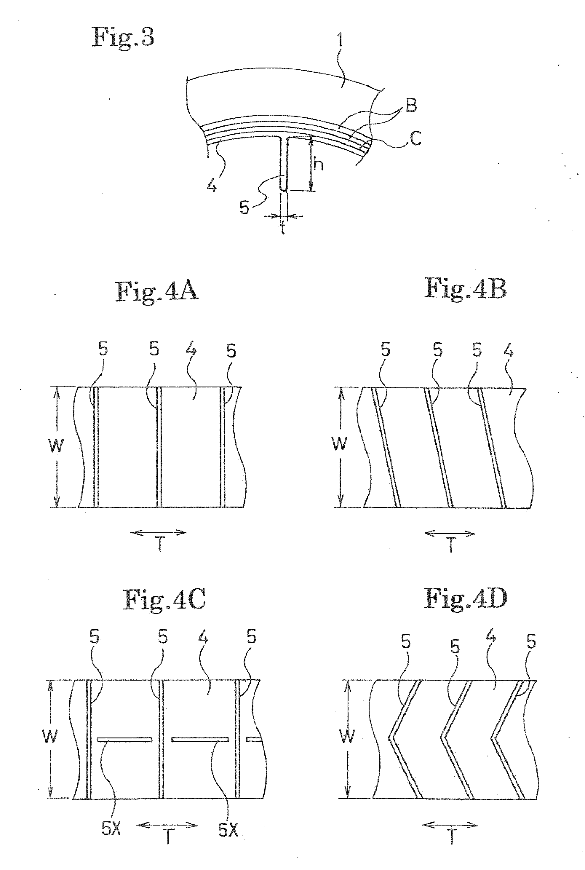
[0066]Tires of the present invention (Examples 1, 2), comparative tires (Comparative Examples 1, 2) and a conventional tire (Conventional Example) were prepared, each tire having a tire size of 215 / 55R17. In the conventional tire (Conventional Example), no convex portions were formed on a tire inner wall surface. In each tire of Examples and Comparative Examples, convex portions were formed at equal intervals on a tire circumference, at 24 spots of a region indicated by W extending across a tire inner wall surface as shown in FIG. 1. The tires of Examples and Comparative Examples differ from one another in specification of the convex portions (arrangements, the number of types of protruding heights, and protruding heights) as shown in Table 1.

[0067]Note that the tires of the present invention and the comparative tires included the convex portions each having a thickness t of 300 μm. In each tire of the present invention, among the 24 convex portions, groups each consisting of eight ...


PUM


Abstract

Provided is a low-noise pneumatic tire for reducing a cavity resonance sound generated inside the tire. An inner liner layer is made of a thermoplastic resin or a thermoplastic elastomer composition formed by blending the thermoplastic resin with an elastomer. Multiple types of convex portions differing from each other in protruding height h are formed on at least a region of an inner wall surface of the inner liner layer, the region corresponding to a tread portion. Each of the convex portions has a strip shape, protrudes from the inner liner layer, and extends in a tire width direction. The convex portions are intermittently arranged in a tire circumferential direction.

Description

BACKGROUND OF THE INVENTION[0001]1. Field of the Invention[0002]The present invention relates to a low-noise pneumatic tire, and more specifically to a low-noise pneumatic tire for reducing a cavity resonance sound generated inside the tire.[0003]2. Description of the Related Art[0004]One of the causes of tire noise is a cavity resonance sound that occurs due to vibration of air filled inside the tire. When the tire rolls under load, a tread portion that comes into contact with a road surface is vibrated by the roughness of the road surface, and this vibration causes the air inside the tire to resonate. Accordingly, the cavity resonance sound is generated. The sound that is heard as a noise in this cavity resonance sound is known to have a frequency around approximately 230 Hz.[0005]Conventionally, as a proposed technique for reducing a noise due to such a cavity resonance phenomenon, a rubber-made partition plate extending in a width direction is provided to a tire inner portion (s...

Claims


Application Information

Patent Timeline
Patent Type & Authority Applications(United States)
IPC IPC(8): B60C9/02
CPCB29D2030/0682B60C19/002B60C5/14
Inventor MATSUNAGA, FUTOSHIMATSUDA, JUN
Owner YOKOHAMA RUBBER CO LTD
Why Eureka
Try Eureka