In-cabinet thermal monitoring method and system

a thermal monitoring and in-cabinet technology, applied in the field of thermal monitoring of electrical equipment, can solve the problems of requiring a trained operator, requiring a large number of thermographic imaging limitations, and a large number of equipment limitations

Active Publication Date: 2010-02-25
ROCKWELL AUTOMATION TECH
View PDF9 Cites 28 Cited by
  • Summary
  • Abstract
  • Description
  • Claims
  • Application Information

AI Technical Summary

Benefits of technology

The present invention offers a cheap and effective way to monitor multiple points of temperature in real-time without requiring constant attention from a person. It uses specialized cameras placed inside equipment cabins, which can detect changes quickly and easily. By utilizing these devices, advanced automation systems are possible that keep tabs on specific parts or processes within the cabinet. Overall, this technology allows for more efficient and accurate heat management at lower costs than traditional methods.

Problems solved by technology

This patent discusses how to use thermographic monitoring to detect heat patterns on electric equipment to alert about possible damage or malfunctions before it occurs. However, there are several challenges related to this technique: the costs involved, the required training of operators, the limited ability to capture all potential issues due to the periodicity of inspectments, and the complexity of installing direct temperature sensors onto equipment.

Method used


Image

  • In-cabinet thermal monitoring method and system
  • In-cabinet thermal monitoring method and system
  • In-cabinet thermal monitoring method and system

Examples


Embodiment Construction

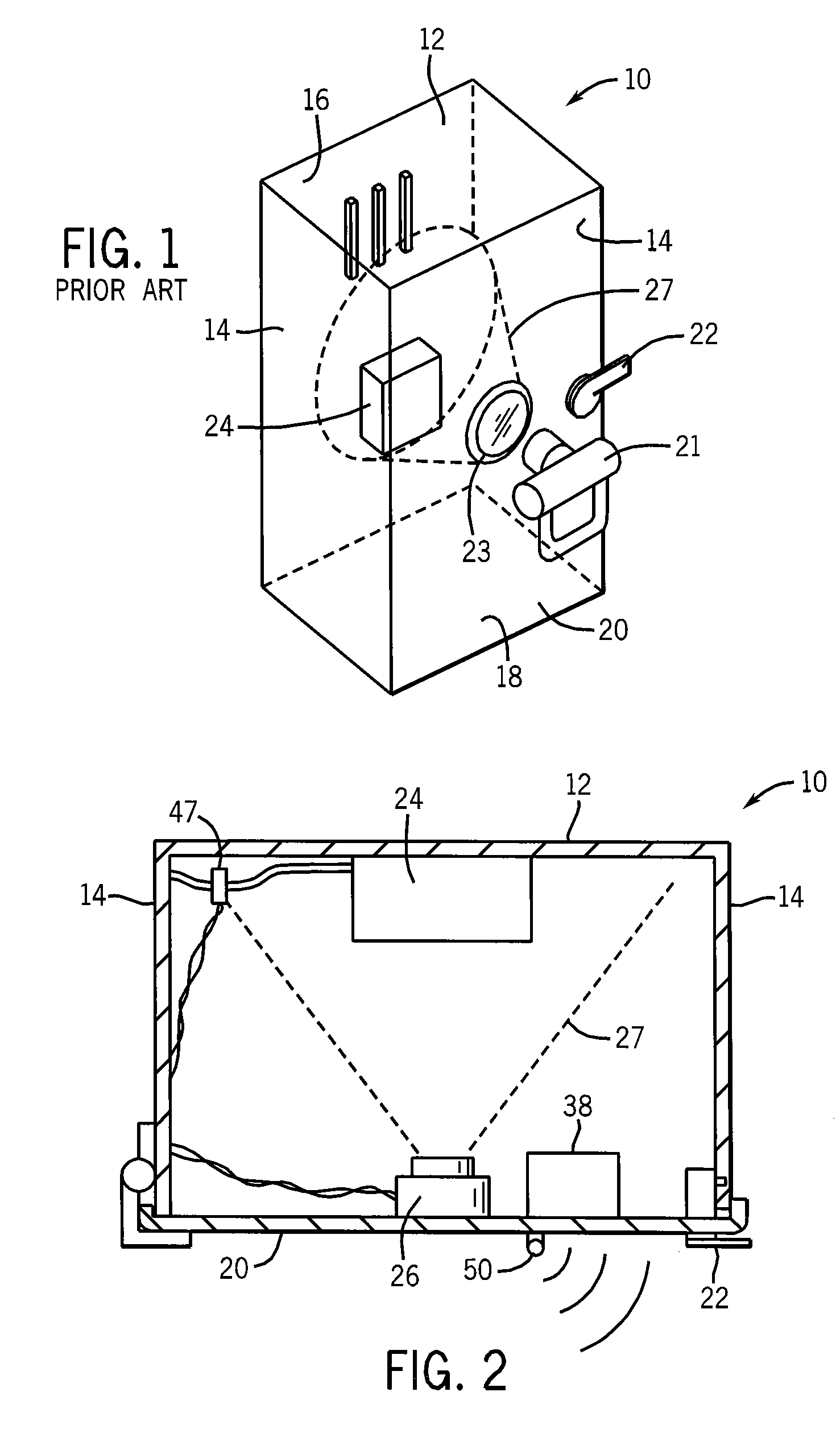
[0042]Referring now to FIG. 1, a switchgear cabinet 10 may have a rear vertical wall providing a mounting panel 12 surrounded by forwardly extending sidewalls 14, top wall 16 and bottom wall 18 to provide a protected volume enclosed by front door 20 opposite the mounting panel 12. Typically the cabinet 10 is constructed of steel panels to provide a strong and fire resistant housing.

[0043]The front door 20 may be opened and closed for access to the enclosed volume in the cabinet 10 by means of a handle 22 which may turn to lock the cabinet 10 and which may be connected to an electrical interlock (not shown) or the like to disconnect power from the cabinet 10 when the door 20 is opened. The door 20 may support a port 23 providing either an infrared transparent window or an openable shutter allowing viewing of internal components by a thermographic camera 21 by a human operator while providing maximum protection to the operator.

[0044]The cabinet 10 may include multiple electrical compo...


PUM


Abstract

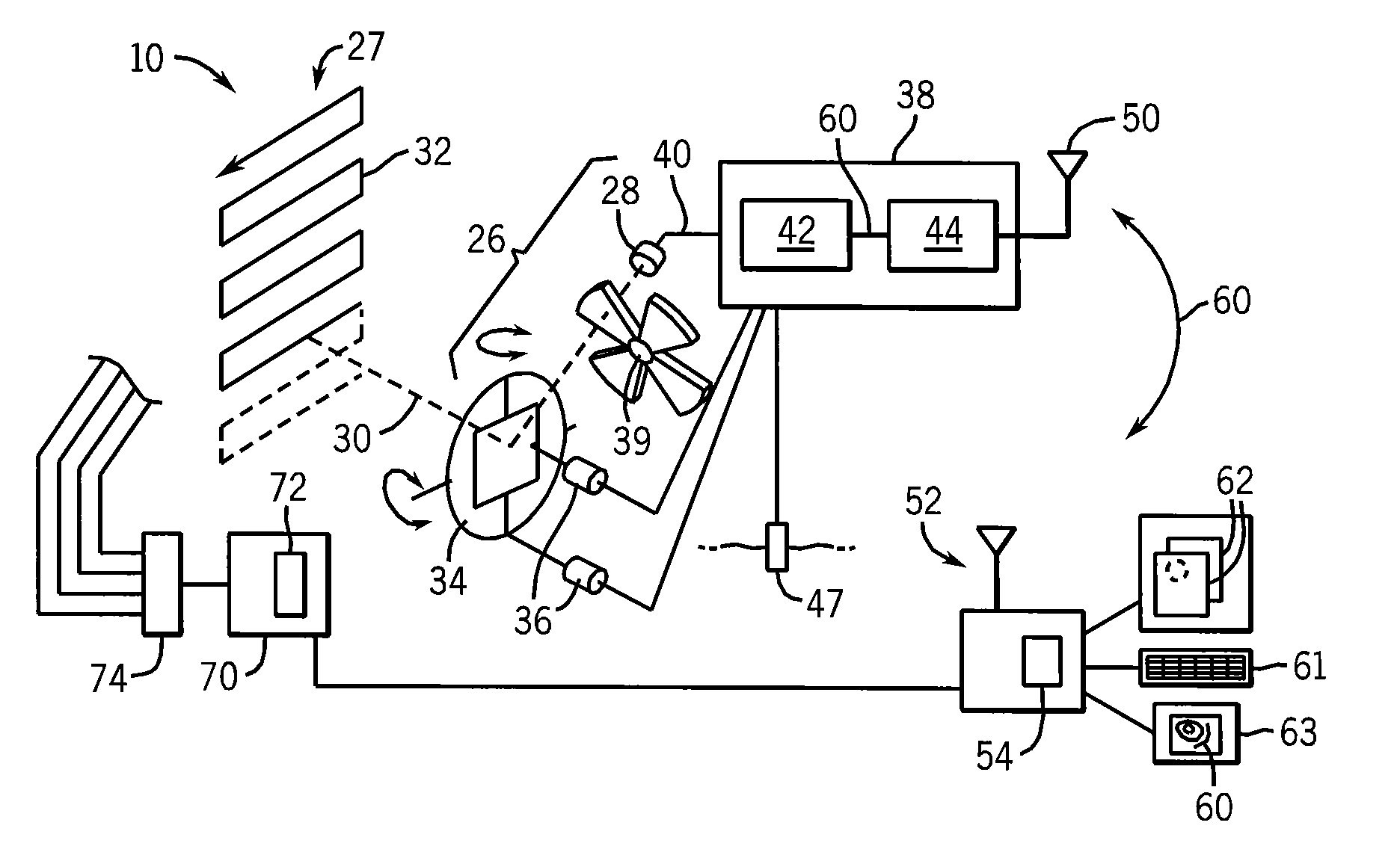
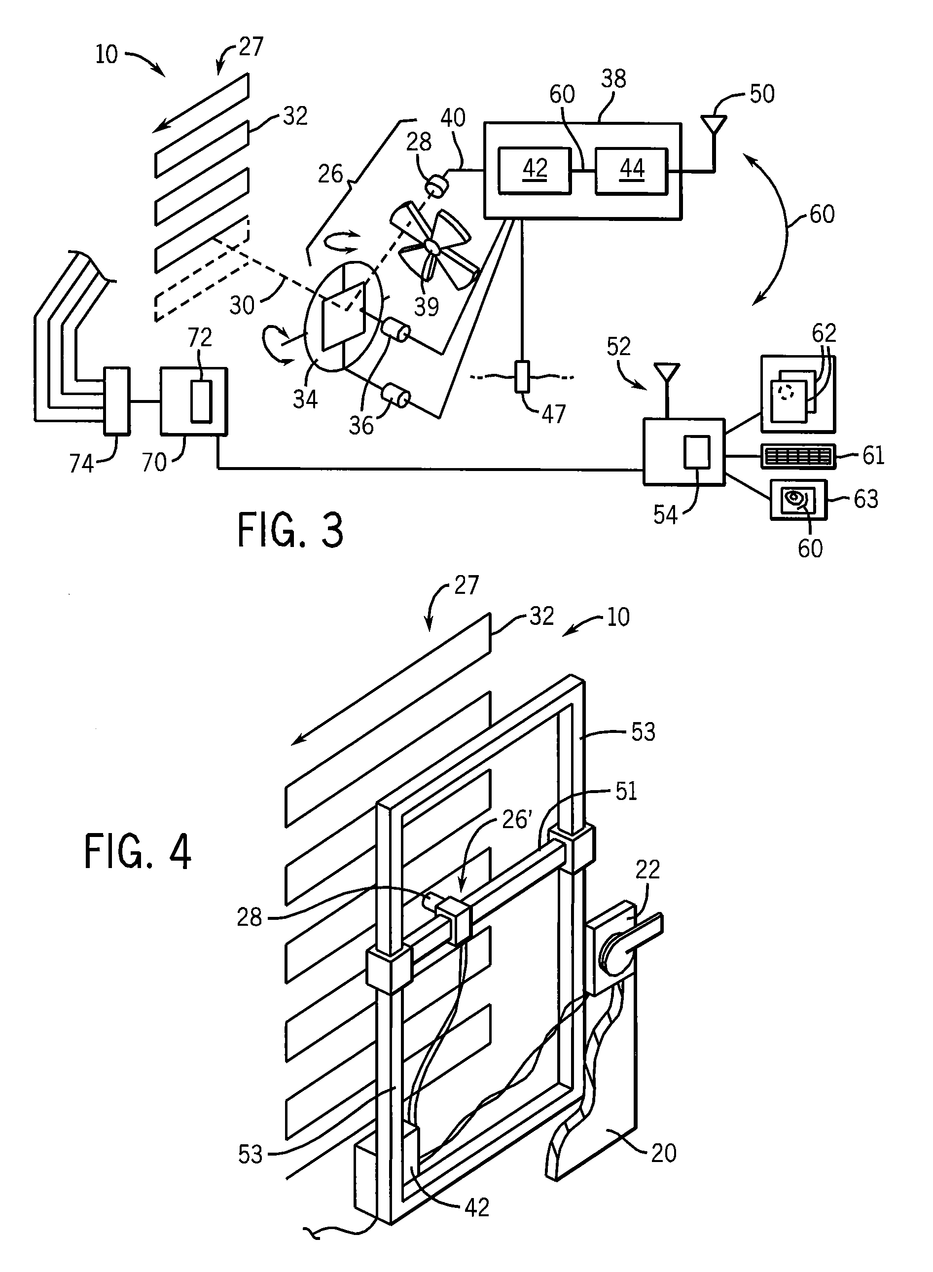
Thermographic imaging equipment is incorporated directly into cabinets housing electrical switchgear to provide for dedicated, nearly continuous monitoring of the contained equipment. A mechanical scanning technique may allow low-cost sensors to provide essentially continuous thermographic monitoring. Dedicated thermal imaging equipment allows automatic analysis through predefined temperature threshold maps.

Description


Claims


Application Information

Patent Timeline
Owner ROCKWELL AUTOMATION TECH
Why Eureka
Try Eureka