Panoramic adapter system and method with spherical field-of-view coverage

Inactive Publication Date: 2010-02-25
RITCHEY KURTIS J
View PDF2 Cites 324 Cited by
  • Summary
  • Abstract
  • Description
  • Claims
  • Application Information

AI Technical Summary

Benefits of technology

[0035]FIG. 21: Diagramatic cutaway perspective of the panoramic adapter optical system with spherical field-of-view coverage in which the optical system incorporate

Problems solved by technology

This is because using more than one camera is typically more expensive than using a single camera.
And plural camera systems require more parts an

Method used


Image

  • Panoramic adapter system and method with spherical field-of-view coverage
  • Panoramic adapter system and method with spherical field-of-view coverage
  • Panoramic adapter system and method with spherical field-of-view coverage

Examples


embodiment 142

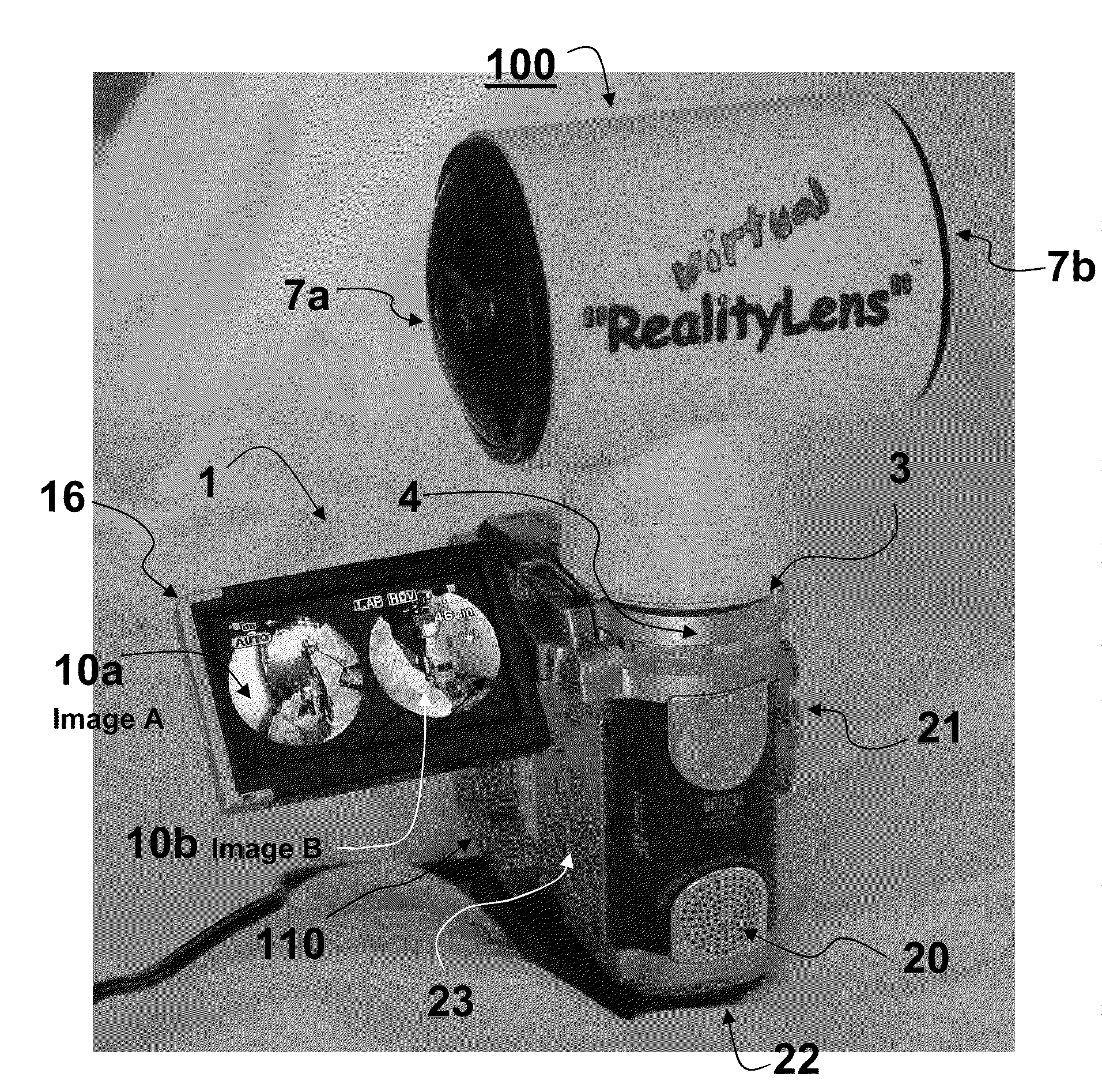
[0117]Still referring to FIG. 24, the digital video signal received from the camera 1, 109, with adapter 100 is received by a host server 139 in an alternative embodiment 142 of the network 125a in which a telecommunications system is integrated with the adapter 100. In operation camera 1 transmits an entire frame with, say images 10a and 10b, to the host server 139, or a subset image / ROI sampled out of images 10a and 10b is read out to the host server 139. Host server 139 systems and LAN / WAN 141 systems for processing information for transmission and reception over communication networks and their components and subcomponents of a type compatible with the present invention are well known in the industry and are used in the present invention. The image or series of images are typically transmitted using conventional telecommunication devices over a Local Area Network or Wide Area Network 141 to a client computer 143. Alternatively, the signal representing the panoramic scene from or...

second embodiment

[0128]One embodiment is that the operator operates the system to engage targets observed within the panoramic imagery using a flat panel display 183′ and joystick 184′ mounted inside the combat vehicle 176. A second embodiment is that the operator 185 wear a head mounted display system 183″ with a position sensing system 184″ that is integrated with the target acquisition and fire control system 182 to engage targets using the weapon system 181 observed within the panoramic imagery recorded by the camera 1 with adapter 100. Head mounted display systems 183″ and 184″ with head and eye tracking devices that transmit roll, pitch, yaw, and heading and xyz coordinates that are able to be received and operated on by a target acquisition and fire control system such as the CROWS system are well known within the art and are incorporated in the present invention. Again referring to FIG. 10 in order conceptualizes one application of using the panoramic imagery from the adapter. In order that ...


PUM


Abstract

A panoramic optical system includes optical means including one or more objective and relay optics to focus at least one image representing at least some portion of a substantially spherical field-of-view scene in focus to an imaging plane, housing means including support means to hold the optical means and mounting means that attaches the panoramic optical system to an adjacent camera.

Description

[0001]This application claims the benefit of, and priority to, U.S. Provisional patent application 60 / 985,867 filed Nov. 6, 2007, U.S. patent application Ser. No. 11 / 836,637 filed Jul. 30, 2007, U.S. patent application Ser. No. 11 / 131,647 filed May 18, 2005 and published as United States Patent Publication Number 2007 / 0182812, U.S. patent application Ser. No. 11 / 354,779 filed Feb. 15, 2006 and published as United States Patent Publication No. 2007 / 0002131, U.S. patent application Ser. No. 11 / 625,208 filed Jan. 19, 2007, U.S. patent application Ser. No. 11 / 829,696 filed Jul. 27, 2007, Ser. No. 11 / 432,647 filed May 11, 2006 and U.S. patent application Ser. No. 11 / 464,736, U.S. patent application Ser. No. 11 / 432,568 entitled “Volumetric Panoramic Sensor Systems” filed May 11, 2006; all filed on the present inventors behalf by Frank. C. Nicholas, Cardinal Law Group, 1603 Orrington, Suite 2000, Evanston, Ill. 60201, Ph. (847) 905-7111. The above applications art all of which in their ent...

Claims


Application Information

Patent Timeline
IPC IPC(8): H04N7/00G02B13/06
CPCG02B13/06G02B15/10H04N5/23238H04N5/2254H04N5/2259G03B37/00H04N23/58H04N23/661H04N23/55H04N23/698
Inventor RITCHEY, KURTIS J.
Owner RITCHEY KURTIS J
Why Eureka
Try Eureka