Fluorescent light fixture retrofit kit

a fluorescent lamp fixture and retrofit kit technology, applied in the direction of fixed installation, lighting and heating equipment, lighting support devices, etc., can solve the problem of lessening the required structural integrity, and achieve the effect of convenient installation

Inactive Publication Date: 2010-02-25
PHILIPS ELECTRONICS NORTH AMERICA
View PDF15 Cites 11 Cited by
  • Summary
  • Abstract
  • Description
  • Claims
  • Application Information

AI Technical Summary

Benefits of technology

[0004]It is an object of the present invention to provide an easil

Problems solved by technology

Since the high efficiency replacement ballast is not supported by the reflector, bu

Method used


Image

  • Fluorescent light fixture retrofit kit
  • Fluorescent light fixture retrofit kit
  • Fluorescent light fixture retrofit kit

Examples


Embodiment Construction

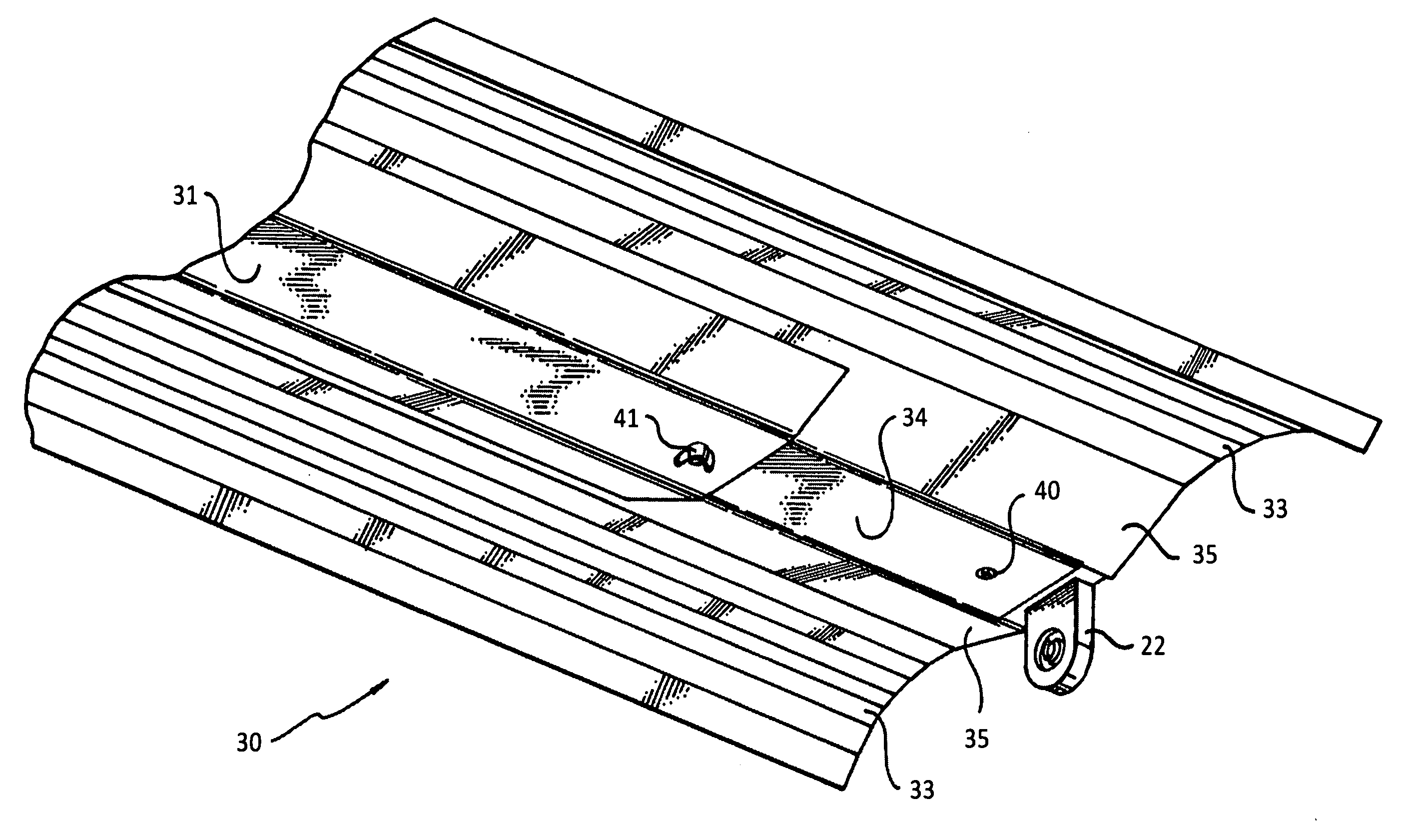
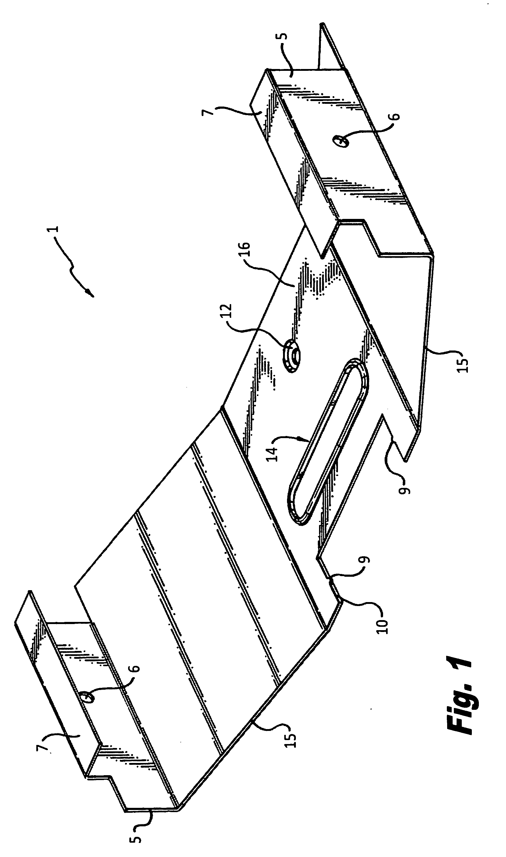
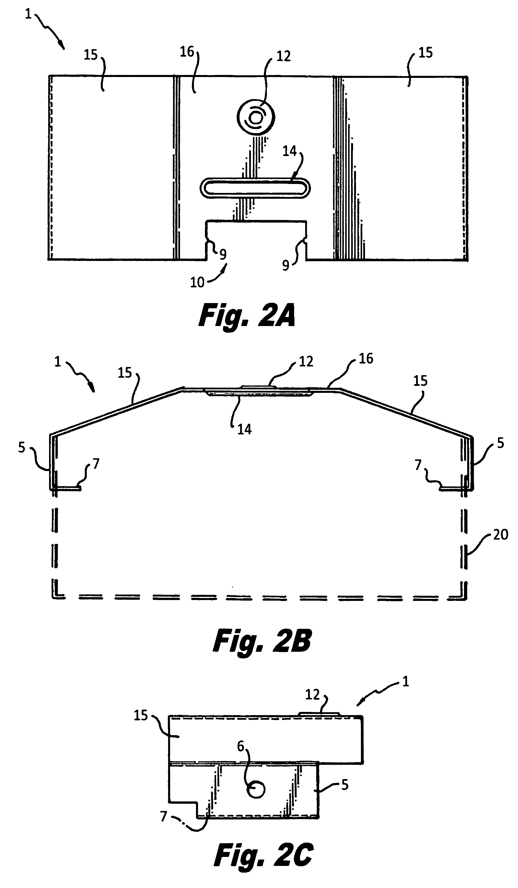
[0022]FIGS. 1 and 2 describe the shape of the arched (trapezoidal) socket bar 1 used at each end of the fixture housing. It is a key structural element as well as a performance element which precisely fixes the location of the lamp socket in relation to the reflector. As a die formed sheet metal part, it is inexpensive to produce. It has sloping sides 15 on either side of horizontal section 16. Vertical walls 5 hug the outside vertical surfaces of the housing while tabs 7 engage the socket bar slots on the sides of the housing. Holes 6 can be used to add attachment screws from socket bar 1 to the housing. A cutout region with side edges 9 used as rails to engage the lamp socket (a type which mounts by side grooves) is part of the horizontal section. Dimples 10 are used to engage the side grooves of the lamp socket for a tight fit. An elongated hole 14 with rounded edges is used as a stiffening feature. Item 12 is an embossed section with a punched slotted hole to accommodate a ¼-tur...


PUM


Abstract

A retrofit kit is configured for a single or multiple tubular fluorescent lamp fixture. The original fixture being retrofitted may or may not have any reflectors. The kit includes a new improved reflector with double concave wings. The winged reflector preferably has a central arched, preferably trapezoidal portion which forms the lower cover of the fixture box. This central trapezoidal portion includes an access door to permit access to the ballast without the need to remove the winged reflector once it is installed. An arched, preferably trapezoidal socket bar is installed at each end of the fixture, to lower the position of the lamp with respect to the winged reflector surfaces, to enhance the light distribution in a downward direction while permitting enhanced up-lighting. The distal ends of the trapezoidal central portion of the reflector mate with the trapezoidal socket bars at opposite ends of the fixture.

Description

RELATED APPLICATIONS[0001]This application is a continuation-in-part of application Ser. No. 12 / 229,390 filed on Aug. 22, 2008 entitled BALLAST ACCESS HATCH IN REFLECTOR, and claims priority under 35 U.S.C. §120 in part therefrom.FIELD OF THE INVENTION[0002]The present invention relates to a retrofit kit for tubular fluorescent lamp fixtures.BACKGROUND OF THE INVENTION[0003]Although the prior art reveals a variety of retrofit kits for fluorescent fixtures, none provide the combination of high efficiency, even light distribution, low cost, and ease of installation of the present invention.OBJECTS OF THE INVENTION[0004]It is an object of the present invention to provide an easily installable a retrofit kit for tubular fluorescent lamp fixtures.[0005]It is an object of the present invention to provide an easily maintainable and accessible retrofit kit for tubular fluorescent lamp fixtures.[0006]It is also an object of the present invention to provide a new improved reflector with enhan...

Claims


Application Information

Patent Timeline
IPC IPC(8): F21V7/00
CPCF21S8/06Y02B20/386F21Y2103/00F21V7/005Y02B20/30
Inventor KASSAY, CHARLES E.PANE, SUZANNE M.KASSAY, MARC A.KASSAY, JOHN P.
Owner PHILIPS ELECTRONICS NORTH AMERICA
Why Eureka
Try Eureka