Nerve cuff injection mold and method of making a nerve cuff

a nerve cuff and injection mold technology, which is applied in the field of chamber nerve cuff injection molds, can solve the problems of nerve cuff damage, nerve damage, and difficulty in precisely determining electrode placement, and achieve the effect of avoiding nerve damag

Inactive Publication Date: 2010-02-25
4491343 CANADA
View PDF5 Cites 97 Cited by
  • Summary
  • Abstract
  • Description
  • Claims
  • Application Information

AI Technical Summary

Problems solved by technology

Fabricating a multi-chamber, multi-channel nerve cuff having one or more independent electrodes in each of several chambers is challenging, especially where the cuff is small in size.
The challenge is compounded by the fact that such cuffs should be fabricated from material which is sufficiently flexible to minimize damage to delicate neural tis

Method used


Image

  • Nerve cuff injection mold and method of making a nerve cuff
  • Nerve cuff injection mold and method of making a nerve cuff
  • Nerve cuff injection mold and method of making a nerve cuff

Examples


Embodiment Construction

[0066]With reference to the associated drawings illustrative embodiments of the present invention will now be described so as to exemplify the invention and by no means limit the scope thereof.

[0067]Generally stated, the invention relates to injection molds for nerve cuffs having interfacing first and second mold cavities with respective molding patterns.

Nerve Cuff Mold (100)

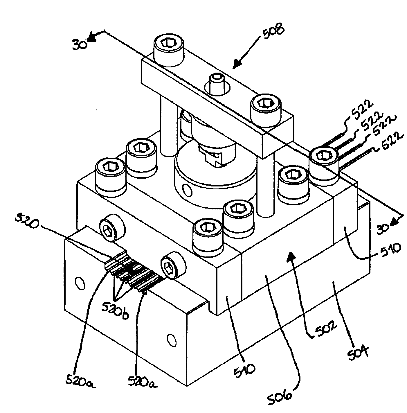
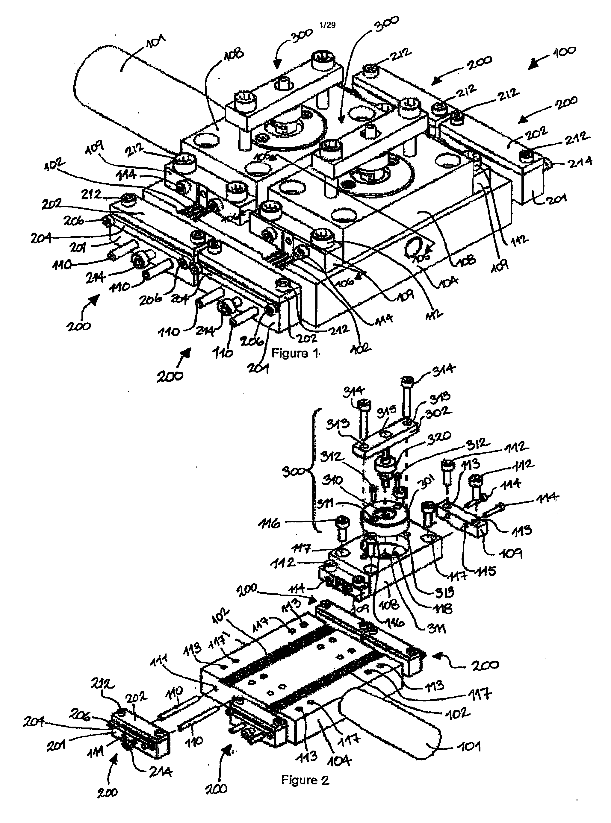
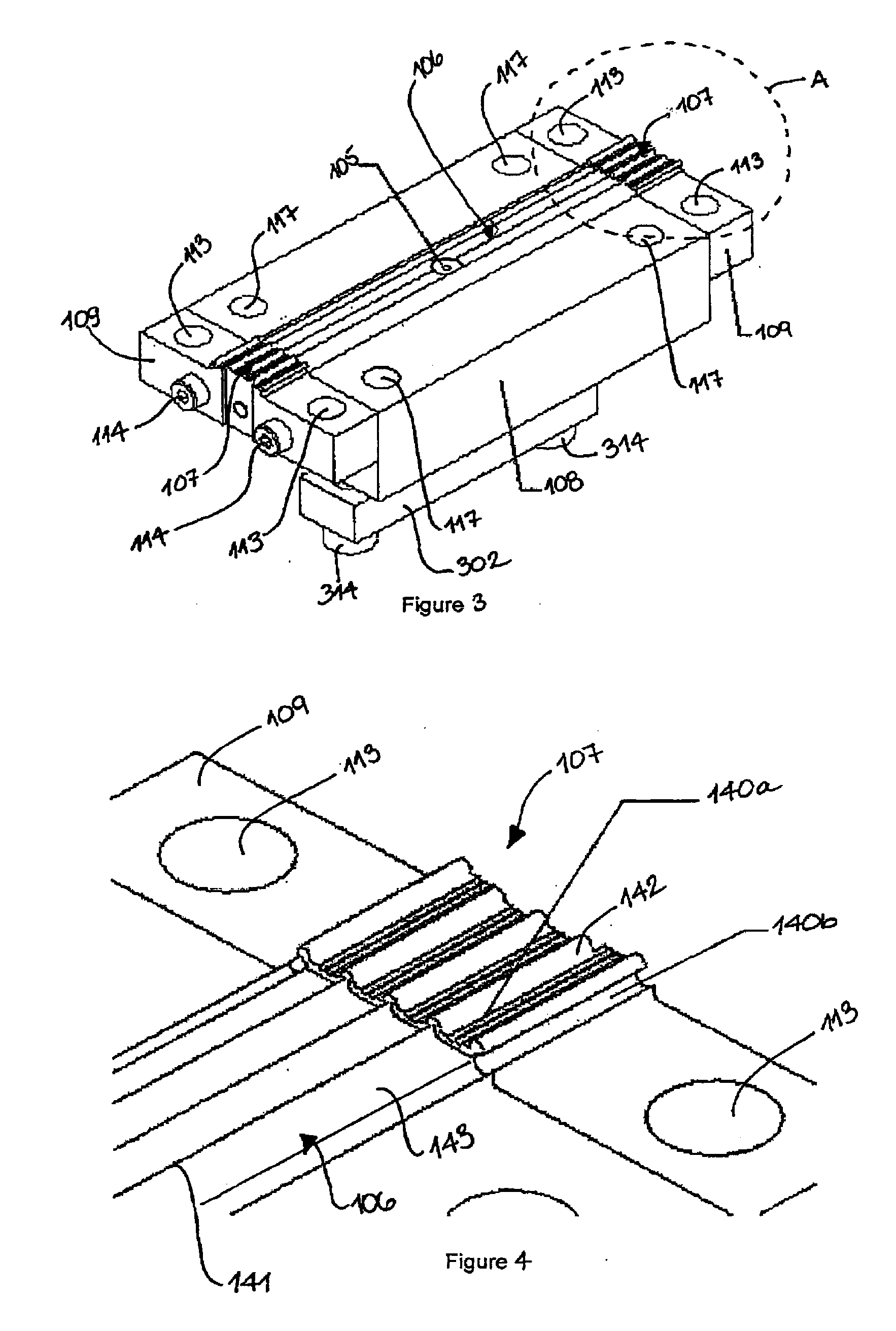
[0068]FIGS. 1 to 3 shows a mold 100 for manufacturing a nerve cuff 1010 (see FIG. 11) by using an injection molding process. In one example, the nerve cuff 1010 is manufactured using rapid-prototyping like injection. The mold 100 Includes bottom molding cavity 102 formed on a first body or base 104, as best shown in FIG. 2, second bodies or injection plates 108 with associated top molding cavity 106, as best shown in FIG. 3, tightness adjustment mechanisms 200 and an injection unit 300. A handle 101 may be used to manipulate the mold 100. Although the illustrated embodiment of the mold 100 shows two bottom moldi...


PUM

PropertyMeasurementUnit
Moldableaaaaaaaaaa

Abstract

A mold for a nerve cuff having a first molding body defining a first molding cavity and a second molding body defining second molding cavity. The first and second molding bodies being mountable to one another thereby providing for the first and second molding cavities to interface. When interfacing the first and second molding cavities and injecting moldable material therebetween provides the nerve cuff following curing of the moldable material. An industrial mold including interfacing first and second cavities is also disclosed. A removable cassette for interposing between a first and a second molding cavity is also disclosed. Methods of making a nerve cuff are disclosed herein. Nerve cuffs produced by the foregoing molds, cassettes, industrial molds and methods are also disclosed.

Description

FIELD OF THE INVENTION[0001]The present invention relates to a nerve cuff injection mold and a method of making a nerve cuff. More specifically but not exclusively, the present invention relates to a chamber nerve cuff injection mold.BACKGROUND OF THE INVENTION[0002]Various types of cuff transducers intended for use as electrical or chemical interfaces with neural tissue have been described in the literature. These nerve cuffs typically have a tubular biocompatible dielectric material wall. In nerve cuffs designed to provide an electrical interface to tissues inside the nerve cuff, the inside of the nerve cuff wall supports one or more metal electrodes. Leads from the electrodes extend through and are supported by the nerve cuff wall. The nerve cuff walls must be sufficiently rigid to support the leads and electrodes. The leads may be connected to suitable signal-conditioning devices or electrical stimulation devices.[0003]Nerve cuff electrodes have been used in stimulation systems ...

Claims


Application Information

Patent Timeline
IPC IPC(8): B29C45/14
CPCA61N1/0556B29C45/0055B29C45/03B29C45/14065B29L2031/753B29C45/14639B29C45/2673B29C2045/0058B29K2083/00B29C45/14426
Inventor IMBEAU, MARC-OLIVIERRICHARD, MARTINVALLIERES, JEAN-MARTIN
Owner 4491343 CANADA
Why Eureka
Try Eureka