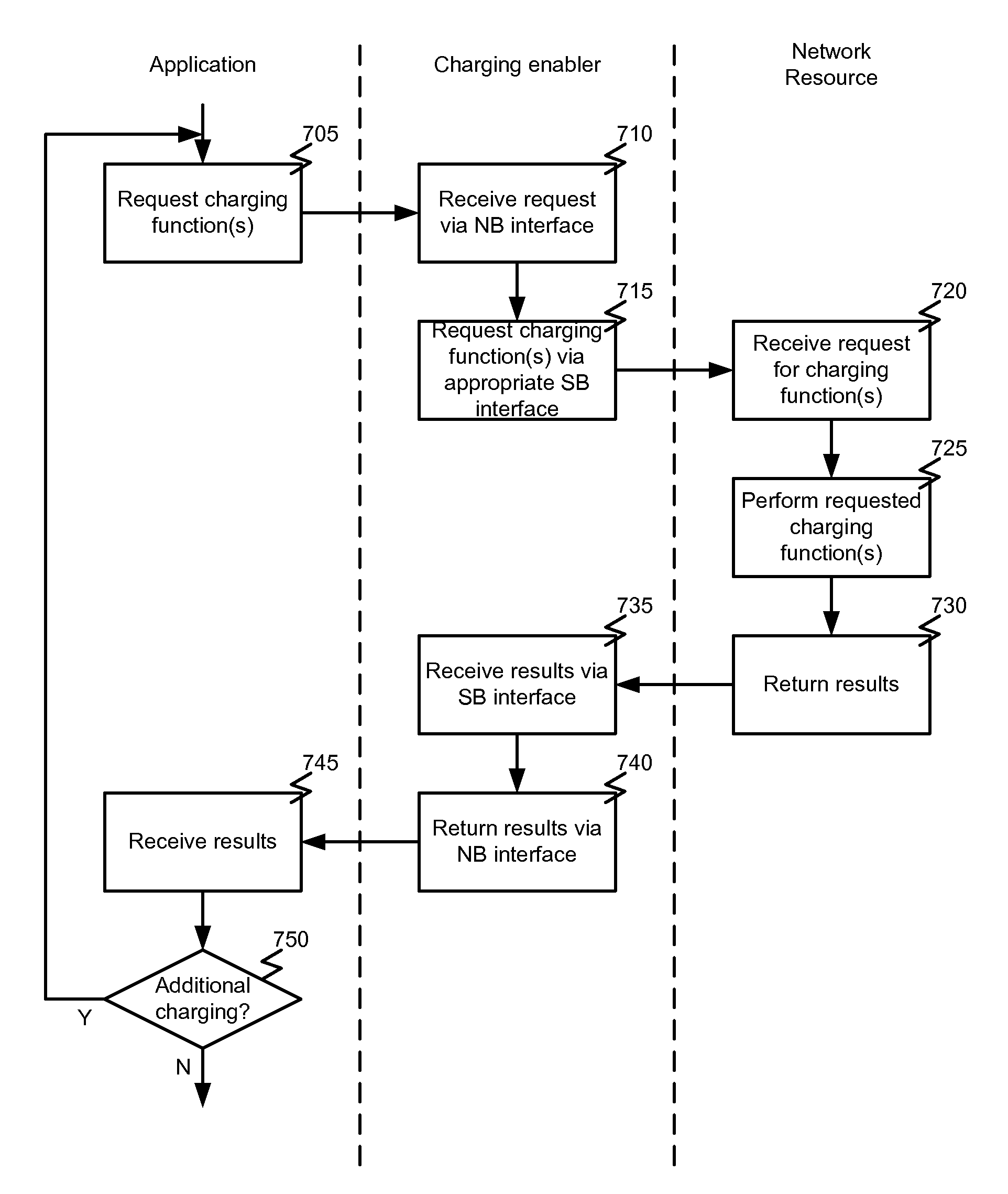
Charging enabler

a charging enabler and enabler technology, applied in the field of charging enablers, can solve the problems of limited current billing or charging systems, unfavorable service layer application usage, and limitations of existing billing systems

Active Publication Date: 2010-02-25
ORACLE INT CORP
View PDF103 Cites 64 Cited by
  • Summary
  • Abstract
  • Description
  • Claims
  • Application Information

AI Technical Summary

Benefits of technology

[0013]In some cases, the system can further comprise a second network resource communicatively coupled with the communications network. In such cases, the charging enabler can be adapted to receive an event notification from the second network resource via the southbound interface of the charging enabler and notify the application of the notification via the northbound interface of the charging enabler. The application can determine one or more charging functions to be performed in response to the notification and request one of the plurality of charging functions via the northbound interface of the charging enabler. The charging enabler can receive the request to perform the one or more charging functions from the application via the northbound interface of the charging enabler and request the charging function from the first network resource via the southbound interface of the charging enabler.

Problems solved by technology

However, these existing billing systems present certain limitations.
For example, current billing or charging systems are limited to particular in network protocols through which applications and / or services are expected to interact with the system.
These however are designed for core services developed in network and not well designed for usage by a service layer application.
Furthermore, these systems limit an application's or service's ability to influence or control the charging and / or billing functions.
That is, these systems provide certain defined functions but and restrict the application or service to use of those functions to any extent they may be provided to the applications or services through their interfaces.

Method used


Image

  • Charging enabler
  • Charging enabler
  • Charging enabler

Examples


Embodiment Construction

[0022]In the following description, for the purposes of explanation, numerous specific details are set forth in order to provide a thorough understanding of various embodiments of the present invention. It will be apparent, however, to one skilled in the art that embodiments of the present invention may be practiced without some of these specific details. In other instances, well-known structures and devices are shown in block diagram form.

[0023]The ensuing description provides exemplary embodiments only, and is not intended to limit the scope, applicability, or configuration of the disclosure. Rather, the ensuing description of the exemplary embodiments will provide those skilled in the art with an enabling description for implementing an exemplary embodiment. It should be understood that various changes may be made in the function and arrangement of elements without departing from the spirit and scope of the invention as set forth in the appended claims.

[0024]Specific details are ...


PUM


Abstract

Embodiments of the invention provide systems and methods for providing charging functions. According to one embodiment, a method of charging for services on a communication network can comprise receiving a request to perform a charging function from an application via a northbound interface of a charging enabler. The northbound interface can provide an abstract interface for invoking one or more of a plurality of charging functions. The charging function can be requested from a network resource via a southbound interface of the charging enabler. The southbound interface can provide an interface specific to the network resource. Results of the charging function can be received from the network resource via the southbound interface of the charging enabler and returned to the application via the northbound interface of the charging enabler.

Description

CROSS-REFERENCES TO RELATED APPLICATIONS[0001]This application claims the benefit of U.S. Provisional Application No. 61 / 090,648, filed Aug. 21, 2008 by Maes and entitled “In-Vehicle Multimedia Real-Time Communications,” of which the entire disclosure is incorporated herein by reference for all purposes.[0002]This application is also related to the following commonly-owned, co-pending applications (the “Related Applications”), of which the entire disclosure of each is incorporated herein by reference for all purposes:[0003]U.S. patent application Ser. No. 10 / 855,999, filed May 28, 2004 by Maes and entitled “Method and Apparatus for Supporting Service Enablers Via Service Request Handholding”; U.S. patent application Ser. No. 11 / 130,636, filed May 16, 2005, by Maes and entitled “Methods and Systems for Exposing Access Network Capabilities Using an Enabler Proxy”; U.S. patent application Ser. No. 11 / 070,317, filed Mar. 1, 2005, by Maes and entitled “Policy Interface Description Framew...

Claims


Application Information

Patent Timeline
Patent Type & Authority Applications(United States)
IPC IPC(8): G06Q30/00G06Q50/00G06Q20/00H04L47/20
CPCG06Q10/06G06Q30/04H04L47/20H04L12/1403H04L47/10H04L12/14H04W4/24H04M15/55
Inventor MAES, STEPHANE H.
Owner ORACLE INT CORP
Why Eureka
Try Eureka