

Wearable firestarter
a firestarter and wearable technology, applied in the field of wearable firestarters, can solve the problems of not carrying conventional firestarter materials, not being carried on an everyday basis, and the firestarter tool is bulkier than the magnesium block, so as to improve the appreciation of the contribution to the art
- Summary
- Abstract
- Description
- Claims
- Application Information
AI Technical Summary
Benefits of technology
Problems solved by technology
Method used
Image

Examples
second embodiment
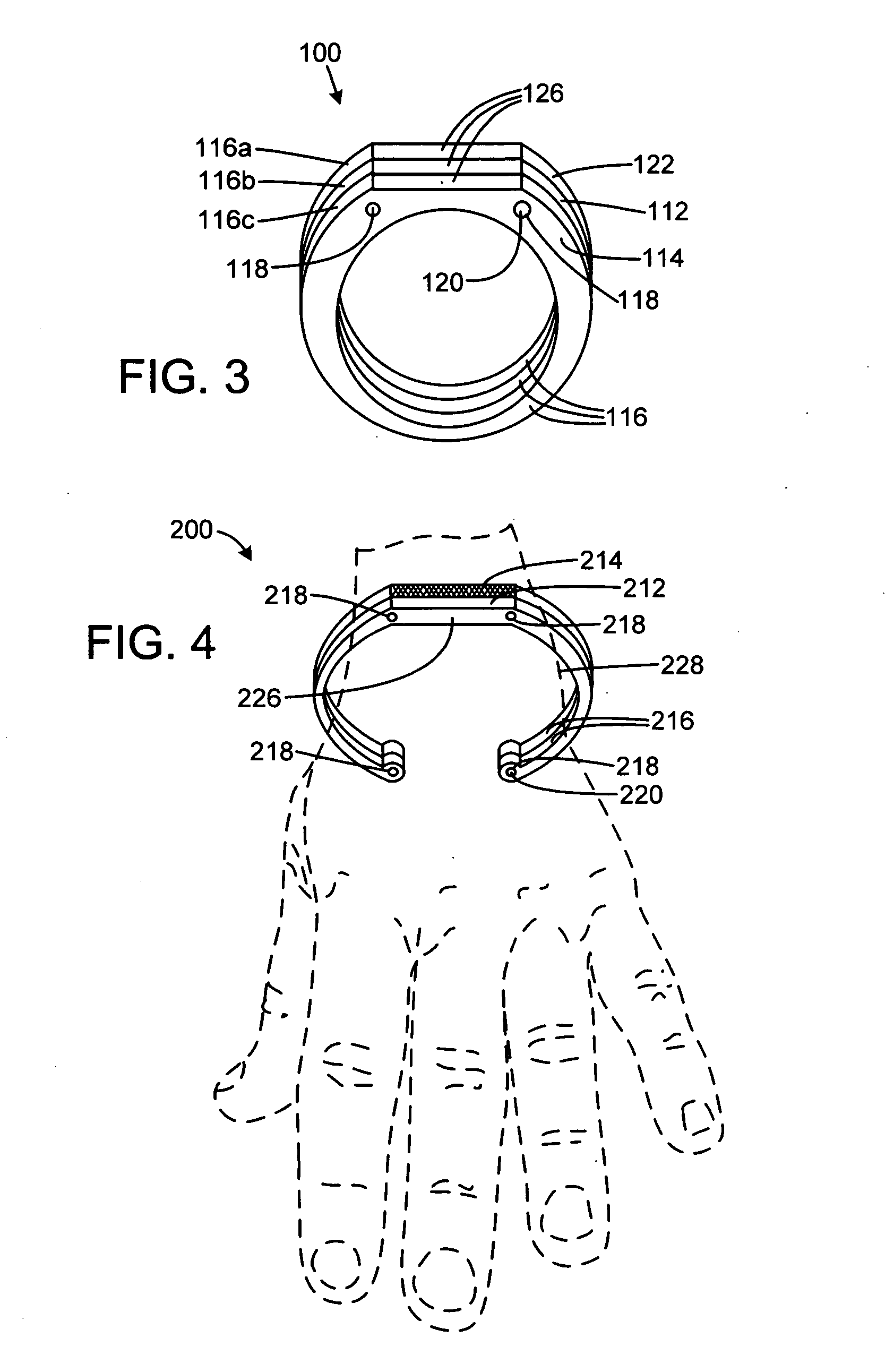
[0028]FIG. 4 illustrates a second alternative embodiment of the improved wearable firestarter 200 of the present invention. More particularly, the wearable firestarter 200 has two wearable portions 216, each having a flat surface forming a face 226. One wearable portion 216 has a sparking material layer 212 attached to its face 226, and the other wearable portion 216 has a striking element layer 214 attached to its face 226. The two wearable portions 216 are releasably joined by retaining pins 220 inserted into pinholes 218 present in the wearable portions 16. The wearable firestarter 200 is depicted being worn on a wearer's appendage 228, which is a wrist in the current embodiment. The wearable firestarter 200 closely encompasses the wearer's appendage. The wearable portions 216 also provide convenient handles that can be gripped when striking the striking element layer 214 against the sparking material layer 212. When used as a handle, the wearable portions 216 have the additional...
third embodiment
[0030]FIG. 6 illustrates a third alternative embodiment of the improved wearable firestarter 300 of the present invention. More particularly, the wearable firestarter 300 has a wearable portion 316 that closely encompasses the wearer's appendage, which is a wrist in the current embodiment. The opposing ends of the wearable portion 316 have pinholes 318 that receive retaining pins 320. A striking element layer 314 and sparking material layer 312 are releasably joined to the wearable portion 316 by hooks 328. A combustible layer 326 is attached to the underside of the sparking materials layer 312. When the wearable firestarter 300 is used for fire starting, the sparking material layer 312 may be reattached to the wearable portion 316 so the wearable portion 316 can be used as a handle. In the current embodiment, the sparking material layer 312 is ferrocerium, the striking element layer 314 is roughened file steel, and the combustible layer 326 is magnesium.
[0031]FIG. 7 illustrates the...
fourth embodiment
[0032]FIG. 8 illustrates a fourth alternative embodiment of the improved wearable firestarter 400 of the present invention. More particularly, the wearable firestarter 400 has a wearable portion 416 that closely encompasses the wearer's appendage, which is a wrist in the current embodiment. The opposing ends of the wearable portion 416 terminate in hooks 418. A striking element layer 414 and a sparking material layer 412 with a combustible layer 426 attached to its underside are releasably joined to the wearable portion 416. When the wearable firestarter 400 is used for fire starting, the sparking material layer 412 may be reattached to the wearable portion 416 so the wearable portion 416 can be used as a handle. In the current embodiment, the sparking material layer 412 is ferrocerium, the striking element layer 414 is roughened file steel, and the combustible layer 426 is magnesium.
[0033]FIG. 9 illustrates the fourth alternative embodiment of the improved wearable firestarter 400 ...
PUM
 Abstract
Description
Claims
Application Information