Arrangements for pumping fluids from sumps

Active Publication Date: 2010-03-04
KIRLOSKAR BROTHERS LTD
View PDF5 Cites 0 Cited by
  • Summary
  • Abstract
  • Description
  • Claims
  • Application Information

AI Technical Summary

Benefits of technology

[0018]A still further object of the present invention is to minimize the need to monitor the submergence lev

Problems solved by technology

However, the nature of the floating raft and the fact that it is floating does not fully eliminate the problem of air entrainment.
This method is however expensive & requires ad

Method used


Image

  • Arrangements for pumping fluids from sumps
  • Arrangements for pumping fluids from sumps
  • Arrangements for pumping fluids from sumps

Examples


Example

EXAMPLE 1

[0043]An arrangement for pumping water was provided in a sump. The sump consisted of a reservoir having height 1.43 m, length 9 m & width 0.55 m. A suction pump having capacity 52.5 lps was employed. The pump was installed at a level close to the base of the sump. A draft tube with outlet diameter 0.145 m (inlet being rectangular having cross section 0.427 m×0.187 m) was used. The effective maximum height of the opening of the draft tube in the sump was 0.188 m Water was filled in the reservoir till a level of 1.4 m. The pump was run at duty flow. It was observed that the air entrainment in the form of bubbles and voids started forming and entering the draft tube when the submergence level (critical submergence level) reached at 0.78 m. At this stage the pump was switched off.

Example

EXAMPLE 2

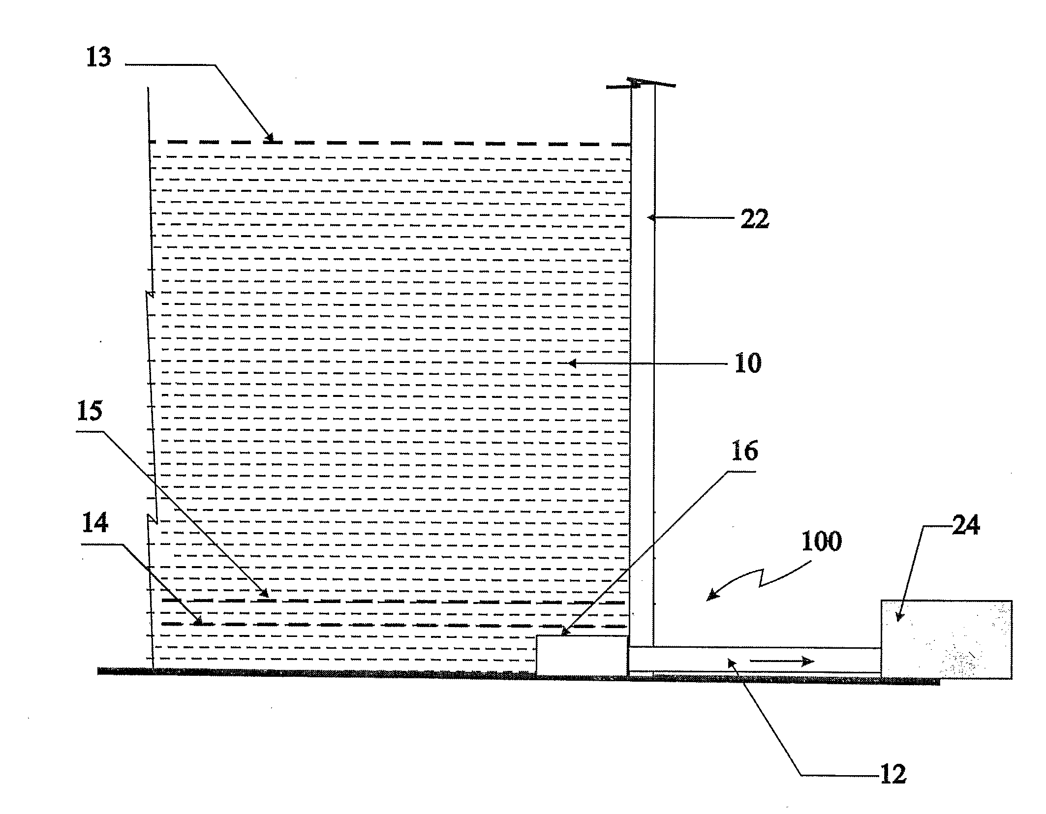
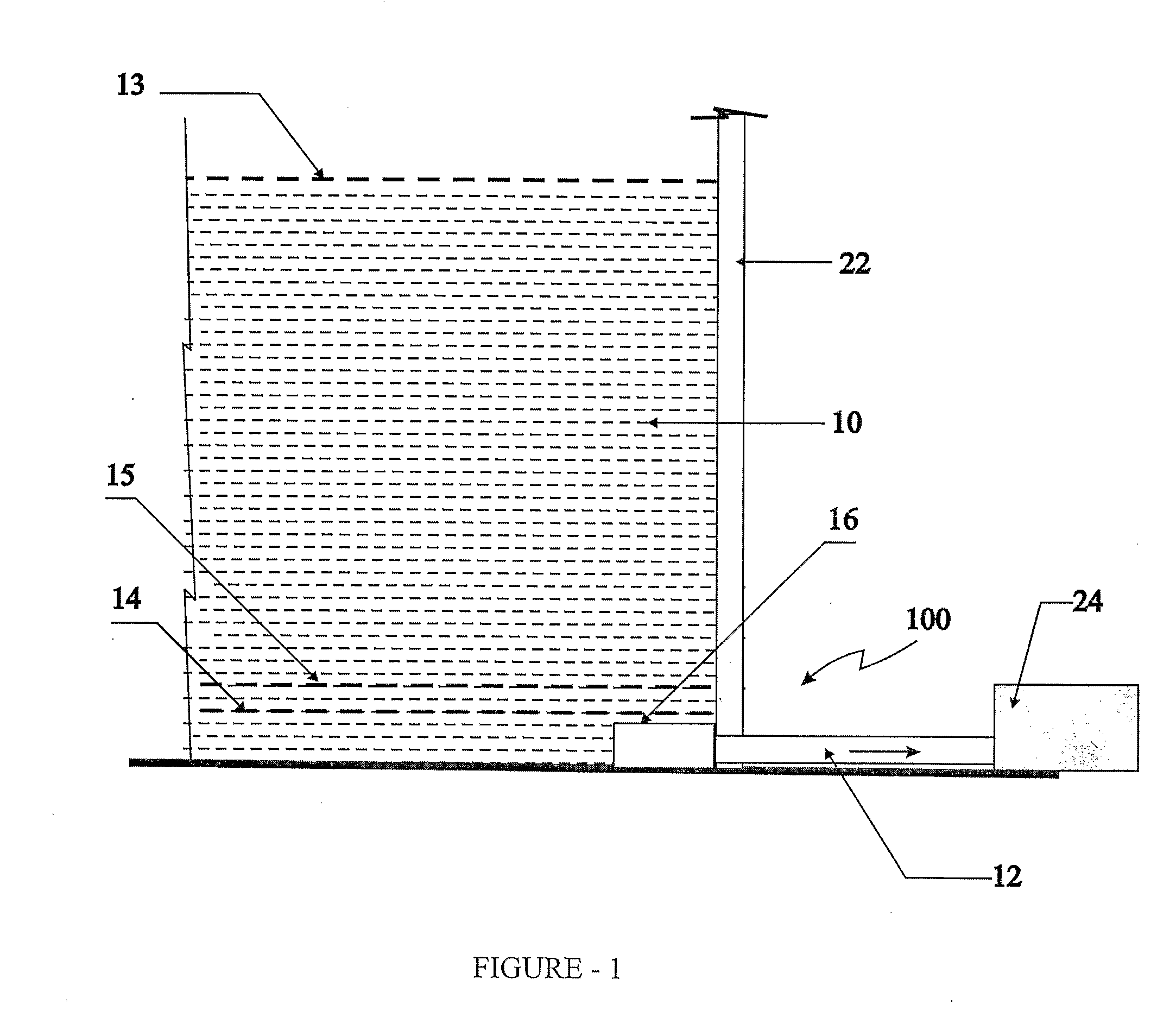
[0044]An arrangement as described in example 1 was employed. A canopy was positioned at a height of 0.188 m from the bed of the sump with the roof at an angle of 0° to the operative horizontal and the canopy extended at an operative horizontal distance of 0.2 m. The pump was run at the same rpm as in example 1. It was observed that air entrainment in the form of bubbles and voids started entering at a lower submergence level of 0.715 m.

Example

EXAMPLE 3

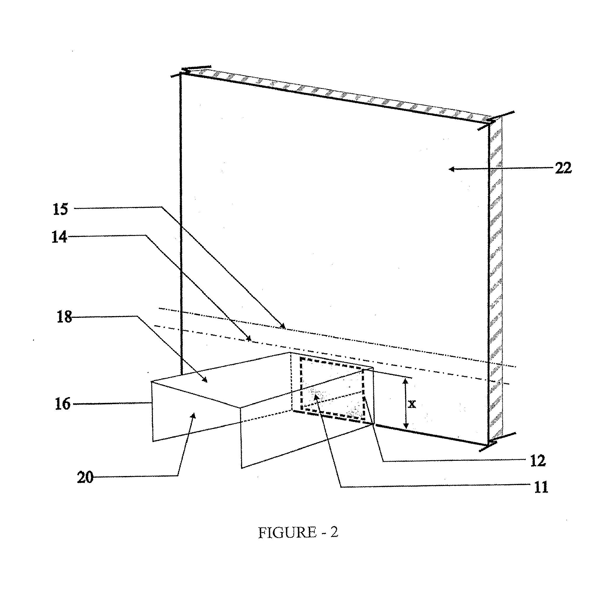
[0045]An arrangement as described in example 2 was employed. The canopy had a rectangular roof and the sidewalls perpendicular to the roof was positioned at a height of 0.2 m from the bed of the sump at an operative horizontal angle of 10° and the canopy extended at an operatively horizontal distance of 0.2 m. It was observed that the air entrainment in the form of bubbles and voids started entering at a submergence level of 0.71 m.


PUM


Abstract

An arrangement for drawing fluid from a sump (10), comprising a pump (24), a draft tube (12) extending from the pump (24), into the sump (10), said draft tube (12) having an opening within the sump (10) and a canopy defined by roof and side walls surrounding said opening.

Description

FIELD OF INVENTION[0001]The present invention relates to arrangements for pumping fluids from sumps.DEFINITION[0002]In the specification unless or otherwise provided, the following terms shall have the meanings assigned to them, in addition to their ordinary dictionary meaning,[0003]Air entraining vortices—The term air entraining vortices refers to vortices that carry cavitation causing voids or air bubbles in a liquid which rapidly collapses, producing a shock wave, thereby causing damage to the impellers of a suction pump.[0004]Cavitation—The term cavitation is used to describe the behavior of voids or bubbles in a liquid. Cavitation is usually divided into two classes of behavior: inertial (or transient) cavitation and non-inertial cavitation. Inertial cavitation is the process where a void or bubble in a liquid rapidly collapses, producing a shock wave.[0005]Draft tube—The term draft tube refers to the tube carrying a liquid such as water from a vessel or body of water such as a...

Claims


Application Information

Patent Timeline
IPC IPC(8): B67D7/58F16L9/00
CPCF04D29/605Y10T137/86067Y10T137/86348
Inventor SHRIVASTAV, RAMESH KUMARKSHIRSAGAR, JAGADISH TRIMBAKSHUKLA, SHYAM NARAYAN
Owner KIRLOSKAR BROTHERS LTD
Why Eureka
Try Eureka