Fluid delivery valve system and method

Inactive Publication Date: 2013-08-15
HYDROPAC LLC
View PDF23 Cites 3 Cited by
  • Summary
  • Abstract
  • Description
  • Claims
  • Application Information

AI Technical Summary

Benefits of technology

[0023]The present invention satisfies these needs. Briefly stated, in accordance with an embodiment of the invention, a fluid delivery system for delivering a fluid to an animal caging system for housing an animal is described. The fluid delivery system may comprise a fluid delivery valve assembly adapted to be coupled to a fluid bag holding a fluid. Without limitation, the fluid delivery valve assembly may

Problems solved by technology

For example, chlorination of the water supply can be useful for some species but toxic to others.
Related caging system technologies for water or fluid delivery have certain deficiencies such as risks of contamination, bio-containment requirements, DNA hazardous issues, gene transfer technologies disease induction, allergen exposure in the workplace and animal welfare issues.
This massive storage, cleaning and sterilization effort, typically performed on a weekly basis, requires large amounts of time, space and human resources to perform these repetitive, and often tedious tasks.
Further, glass bottles (and the handling thereof) can be dangerous and also relatively costly.
Bottle washing machines, bottle fillers, wasted water, hot water, wire baskets to hold bottles, sipper tubes, rubber stoppers, the ergonomic concerns of removing stoppers, screw caps insertion of sipper tubes are all problems inherent to the use of water bottles to provide water to animals.
With respect to automatic water systems, although automatic water systems are available, the cost per cage is too costly for many institutions.
Moreover, the stainless steel parts, such as the valves, require periodic repair.
This adds significantly to the institution's costs.
The human factors of handling wire baskets while load

Method used


Image

  • Fluid delivery valve system and method
  • Fluid delivery valve system and method
  • Fluid delivery valve system and method

Examples


Example

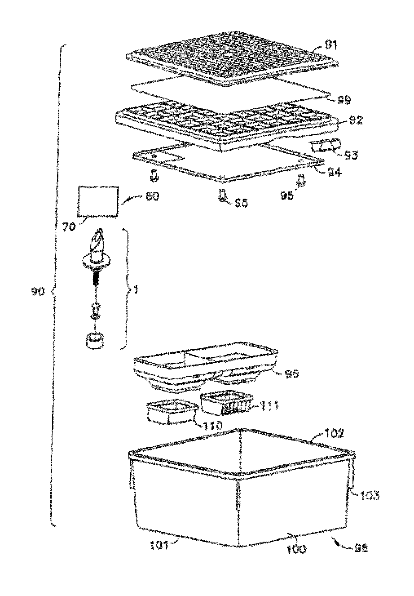
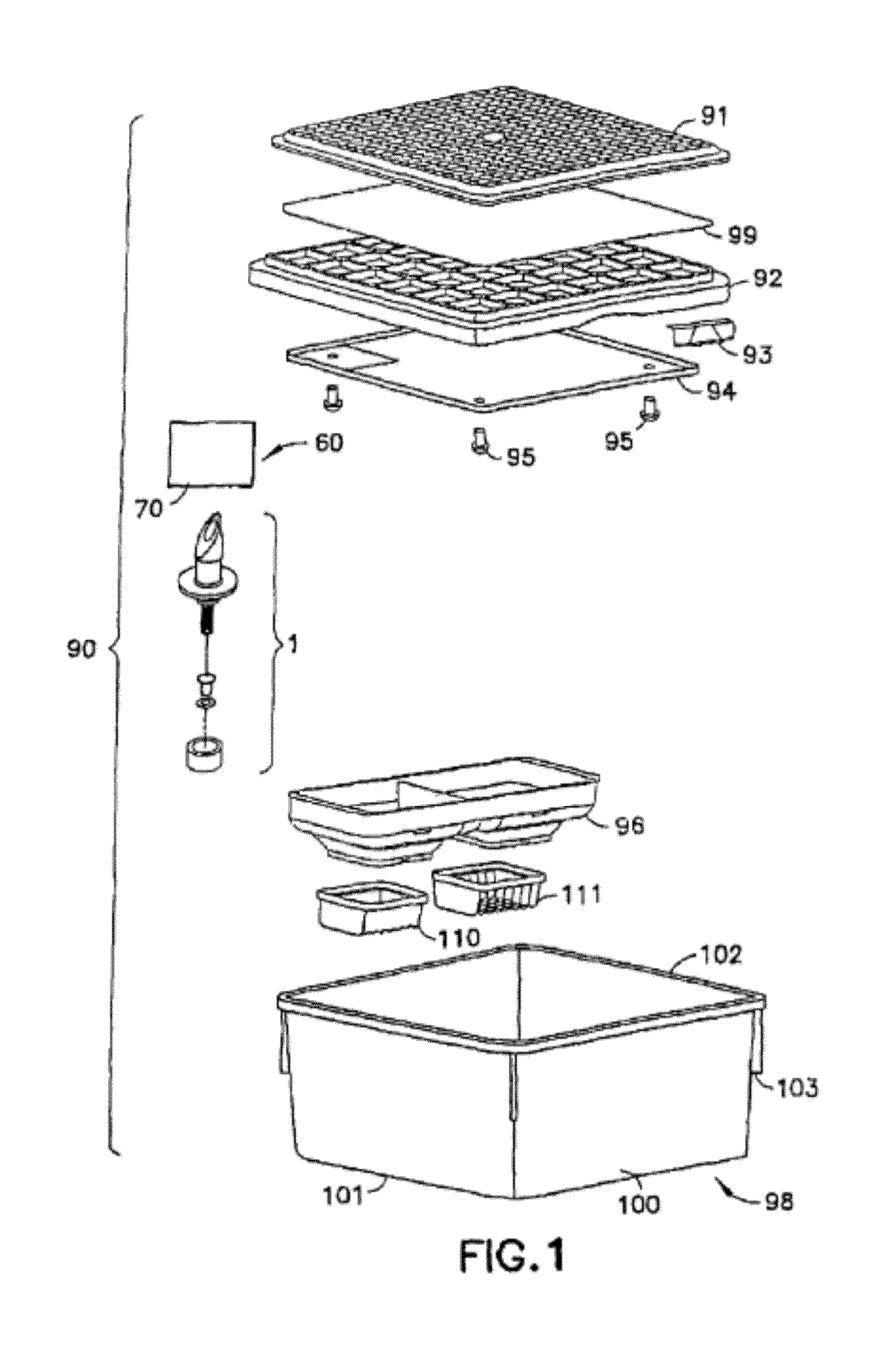
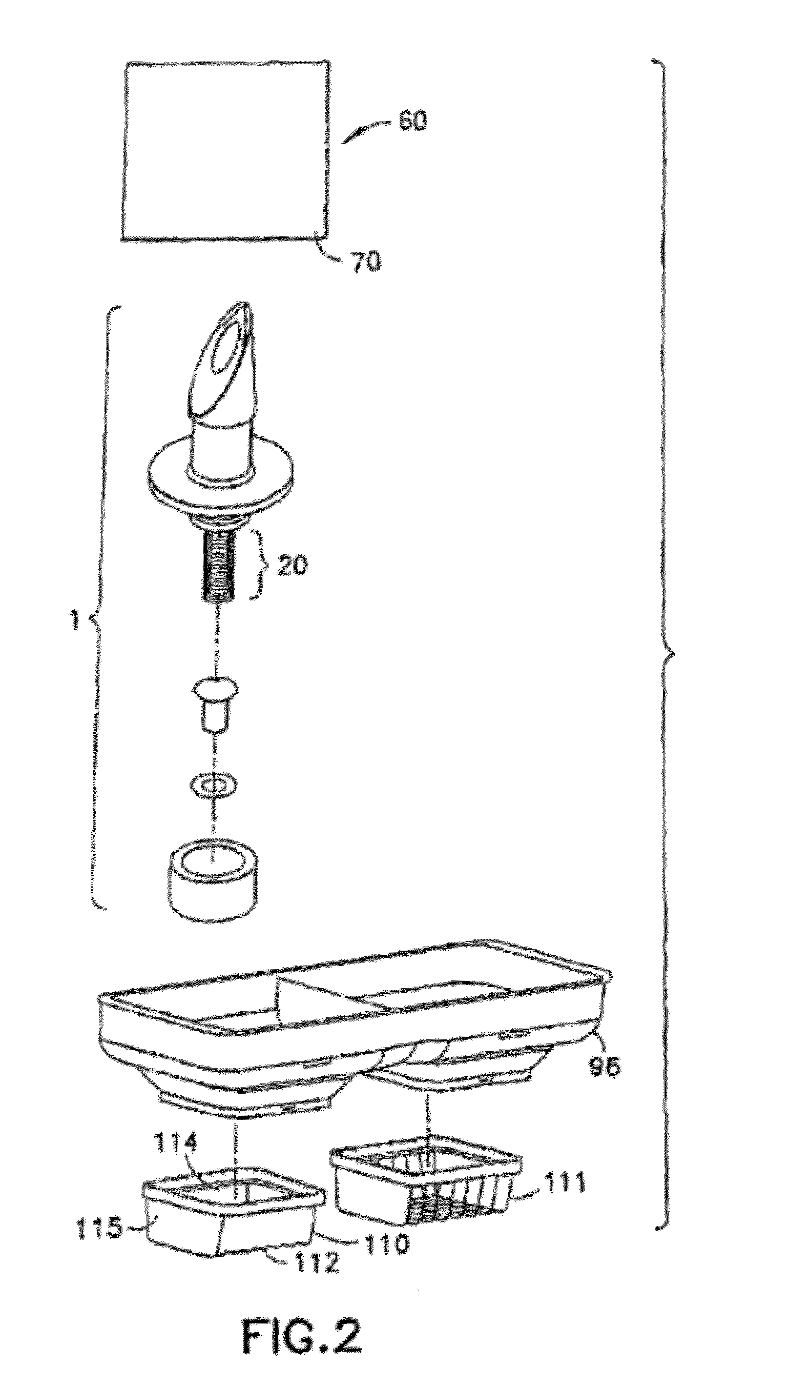
[0110]Reference is made to FIGS. 1 and 2, wherein an animal cage assembly 90, which incorporates fluid delivery valve assembly 1, is shown. Cage assembly 90 incorporates a filter retainer 91, a filter frame 92, a filter top lock 93, a chew shield 94, a plurality of snap rivets 95, a fluid bag 60 containing fluid 70, a fluid delivery valve assembly 1, a diet delivery system 96 providing support member 50, a chow receptacle 111, a fluid bag receptacle 110, and a cage body 98. Cage body 98 comprises a box-like animal cage with a combination diet delivery system 96 capable of providing both food and fluid to animals within cage assembly 90. A filter 99 is also generally provided with cage assembly 90 sandwiched between filter retainer 91 and filter frame 92. Cage body 98 is formed with integral side walls 100, a bottom wall or floor 101 and an open top end. The open top of cage body 98 is bordered by peripheral lip 102, which extends continuously there around. Cage body 98 may also incl...


PUM


Abstract

A cage-mounted fluid delivery system for delivering a fluid from a water source, such as a fluid bag or an automatic water system, to animals housed in cages in high density caging systems may comprise a fluid delivery valve assembly, wherein the fluid delivery valve assembly is adapted to be coupled to the water source to facilitate the provision of fluid to animals housed in the cages. The cage-mounted fluid delivery valve assembly may further comprise a valve body and end cap, which may be joined together, that define a fluid channel. The cage-mounted fluid delivery valve assembly may further comprise sealing elements, a spring element, and an interior stem disposed at least in part in the fluid channel to open and close the fluid channel.

Description

CROSS-REFERENCE TO RELATED APPLICATIONS[0001]This application is a continuation-in-part of U.S. patent application Ser. No. 13 / 656,278 (Attorney Docket No. 364106 / 0483), entitled METHOD AND SYSTEM OF PROVIDING SEALED BAGS OF FLUID AT THE CLEAN SIDE OF A LABORATORY FACILITY, filed on Oct. 19, 2012; and U.S. patent application Ser. No. 11 / 871,942 (US 2009-0095697 A1), entitled VENTILATED RACK SYSTEM, filed on Oct. 12, 2007, both of which are incorporated herein by reference.[0002]U.S. patent application Ser. No. 13 / 656,278 is a divisional of U.S. Pat. No. 8,291,865 (Attorney Docket No. 364106 / 0466), entitled METHOD AND SYSTEM OF PROVIDING SEALED BAGS OF FLUID AT THE CLEAN SIDE OF A LABORATORY FACILITY, filed Dec. 20, 2010.[0003]U.S. Pat. No. 8,291,865 is a divisional of U.S. Pat. No. 7,866,280 (Attorney Docket No. 364106 / 0389), entitled METHOD AND SYSTEM OF PROVIDING SEALED BAGS OF FLUID AT THE CLEAN SIDE OF A LABORATORY FACILITY, filed Sep. 11, 2007.[0004]U.S. Pat. No. 7,866,280 is t...

Claims


Application Information

Patent Timeline
IPC IPC(8): F16K51/00A01K7/00
CPCA01K1/031A01K39/0213B62B3/006A47B2200/06B62B2204/00F16K51/00A01K7/00B62B2202/42B62B2204/02A01K7/06
Inventor GABRIEL, GEORGE S.CAMPBELL, NEIL E.GERRINGER, RODNEY E.IRWIN, LYNN B.ELDRETH, EDWARD K.
Owner HYDROPAC LLC
Why Eureka
Try Eureka