Method and apparatus for performing confinement by thermal stratification

Inactive Publication Date: 2002-01-03
CIE GEN DES MATIERES NUCLEAIRES SA
View PDF0 Cites 4 Cited by
  • Summary
  • Abstract
  • Description
  • Claims
  • Application Information

AI Technical Summary

Benefits of technology

[0036] The person skilled in the art understands that several variants are possible for said means for maintaining the top and bottom volumes of the enclosure at the suitable temperatures, and that, in any event, it is advantageous to insulate said top volume thermally. It is advantageous firstly to reduce heat exchange and secondly to avoid too large a temperature difference between said walls of said top volume and the ambient atmosphere. Such a large temperature difference would give rise to convection currents and to harmful turbulence.
[0045] In variant c), two series of slots are provided in the bottom and / or the top of vertical walls of the enclosure. These slots are distributed in staggered manner (the two series are advantageously uniformly offset) so as to minimize the turbulence generated on injection. Advantageously, the slots that are provided in the bottom volume of the enclosure are not at floor (or false floor) level, but rather they are slightly above floor (or false floor) level. This avoids stirring up any dust that has settled on said-floor (or false floor).
[0046] The apparatus of the invention may use the same type or different types of fluid delivery apparatus in the top and bottom volumes of the enclosure. In an advantageous variant, in the volume(s) in which the pollution is generated, namely the top volume and / or the bottom volume, the fluid delivery apparatus is of above type c). This type of apparatus is particularly optimized for minimizing the vertical speed component of the turbulence generated on injection.

Problems solved by technology

Indeed, it would seem unlikely to be possible for it to be achieved, in particular in a gaseous atmosphere which is very sensitive to convection currents and to turbulence.
Preconceived opinion was therefore strongly unfavorable to basing an industrial method of confinement on the natural phenomenon of thermal stratification.

Method used


Image

  • Method and apparatus for performing confinement by thermal stratification
  • Method and apparatus for performing confinement by thermal stratification
  • Method and apparatus for performing confinement by thermal stratification

Examples


Embodiment Construction

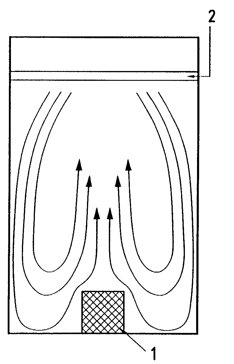
[0065] As shown in FIGS. 1 and 2, the cell contains the pollution source 1 (melting pot and calciner, represented diagrammatically), and the overhead travelling-crane 2 to be protected from said pollution source 1. Said cell is filled with air.

[0066] The technical problem facing the inventors was to limit significantly the contamination of hoists in such cells. The air heated and contaminated by the melting pot and the calciner 1 rises in the cell as it would in a chimney, and insofar as the air is charged with radioactive particles, it contaminates the crane 2 at the top of the cell, thereby making any maintenance operations performed on this equipment much more complex. Experience has shown that the availability of hoists present in cells containing hot pollution sources is related directly to the degree to which they are contaminated.

[0067] In the context of the example, and of the entire research conducted by the Applicant, and whose results are given further on in the present t...


PUM


Abstract

The present invention relates to a method of confining pollution generated in the top volume and / or in the bottom volume of an enclosure filled with a fluid, i.e. either a gas, which is in general air, or a liquid, which is in general water, the method confining the pollution by thermal stratification. In said method the mean temperature of said top volume is maintained higher than the mean temperature of said bottom volume by an amount that is sufficient to ensure that said two volumes are separated by a turbulent intermediate zone of narrow width, referred to as the "mixing zone", within which a steep temperature gradient is maintained; said intermediate zone constituting a virtual confinement barrier in a horizontal plane. The present invention also relates to apparatus associated with the method.

Description

[0001] The present invention relates to a method and apparatus for performing confinement. It relates more precisely to a method of confining pollution generated in the top volume and / or in the bottom volume of an enclosure filled with a fluid, and to apparatus associated with said method. Said method is industrial and it is original in that it is based on the natural phenomenon of thermal stratification. When it is implemented, it can surprisingly guarantee effective confinement in various contexts, and in particular in the most unfavorable context in which a hot pollution source is disposed at the bottom of an enclosure whose top portion is to be protected from said pollution source. The Applicant has developed the method and apparatus of the invention specially for the context of vitrifying fission products in the nuclear industry, with a view to protecting equipment of the hoist type disposed at the top of the vitrification cell from pollution given off by the melting pot and by...

Claims


Application Information

Patent Timeline
IPC IPC(8): F24F9/00G21F5/002G21F5/005G21F7/00G21F9/02G21F9/22
CPCF24F9/00
Inventor MEHLMAN, GUILLAUMEMELINE, FRANCOIS
Owner CIE GEN DES MATIERES NUCLEAIRES SA
Why Eureka
Try Eureka