Fuel dispensing unit comprising a locking member for retaining a fuel conduit in a locked position

a technology of locking member and fuel conduit, which is applied in the direction of transportation and packaging, liquid transfer devices, couplings, etc., can solve the problems of time-consuming and laborious to mount the fuel conduit in assembly of the fuel dispensing unit, and difficult and time-consuming servi

Active Publication Date: 2017-07-04
DOVER FUELING SOLUTIONS UK LTD
View PDF5 Cites 3 Cited by
  • Summary
  • Abstract
  • Description
  • Claims
  • Application Information

AI Technical Summary

Benefits of technology

[0009]This is advantageous in that the fuel conduit can be securely retained in the fuel dispensing unit in a simple and non-time-consuming manner. The fuel conduit is just guided through the locking member and is thereafter retained in the locked position of the locking member. The tongues of the locking member, more precise the acute edge at the end portion of each tongue, prevent the fuel conduit to be withdrawn. Moreover, this is advantageous in that it is only the obtuse edge of each tongue that engage the fuel conduit in the open position, wherein the risk of the tongues causing any damage to the external annular bead is minimized.
[0010]The angle of the obtuse edge may e.g. be 90°, 100°, 110° or 120° but it is preferably 130° or greater. A greater angle of the obtuse edge makes the edge blunter. A blunt edge is less harmful against the external annular bead.
[0012]Again this is advantageous in that the fuel conduit can be securely retained in the fuel dispensing unit in a simple and non-time-consuming manner. The fuel conduit is just guided through the locking member and is thereafter retained in the locked position of the locking member. The tongues of the locking member prevent the fuel conduit to be withdrawn. Moreover, this is advantageous in that the edgeless end portion of the tongues minimizes the risk of the tongues to cause any damage to the external annular bead when the fuel conduit is guided through the locking member.
[0016]Again this is advantageous in that the fuel conduit can be securely retained in the fuel dispensing unit in a simple and non-time-consuming manner. The fuel conduit is just guided through the locking member and is thereafter retained in the locked position of the locking member. The tongues of the locking member prevent the fuel conduit to be withdrawn. Moreover, this is advantageous in that the end portion of the tongues are made in material having a degree of hardness being less than the degree of hardness of the external annular bead. By forming the tongues according to this the risk of the tongues to cause any damage to the external annular bead when the fuel conduit is guided through the locking member is minimized.

Problems solved by technology

A drawback is that it is time consuming to mount the fuel conduits in the fuel dispensing unit.
Another obvious drawback is that it is difficult and time consuming to service and especially new assembly the fuel dispensing unit, e.g. exchange an old fuel conduit.
A drawback of this method is that it is time consuming to mount the conduit in the fuel dispensing unit.

Method used


Image

  • Fuel dispensing unit comprising a locking member for retaining a fuel conduit in a locked position
  • Fuel dispensing unit comprising a locking member for retaining a fuel conduit in a locked position
  • Fuel dispensing unit comprising a locking member for retaining a fuel conduit in a locked position

Examples


first embodiment

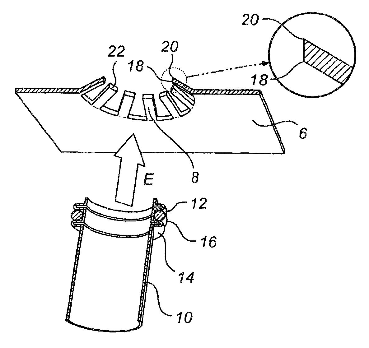
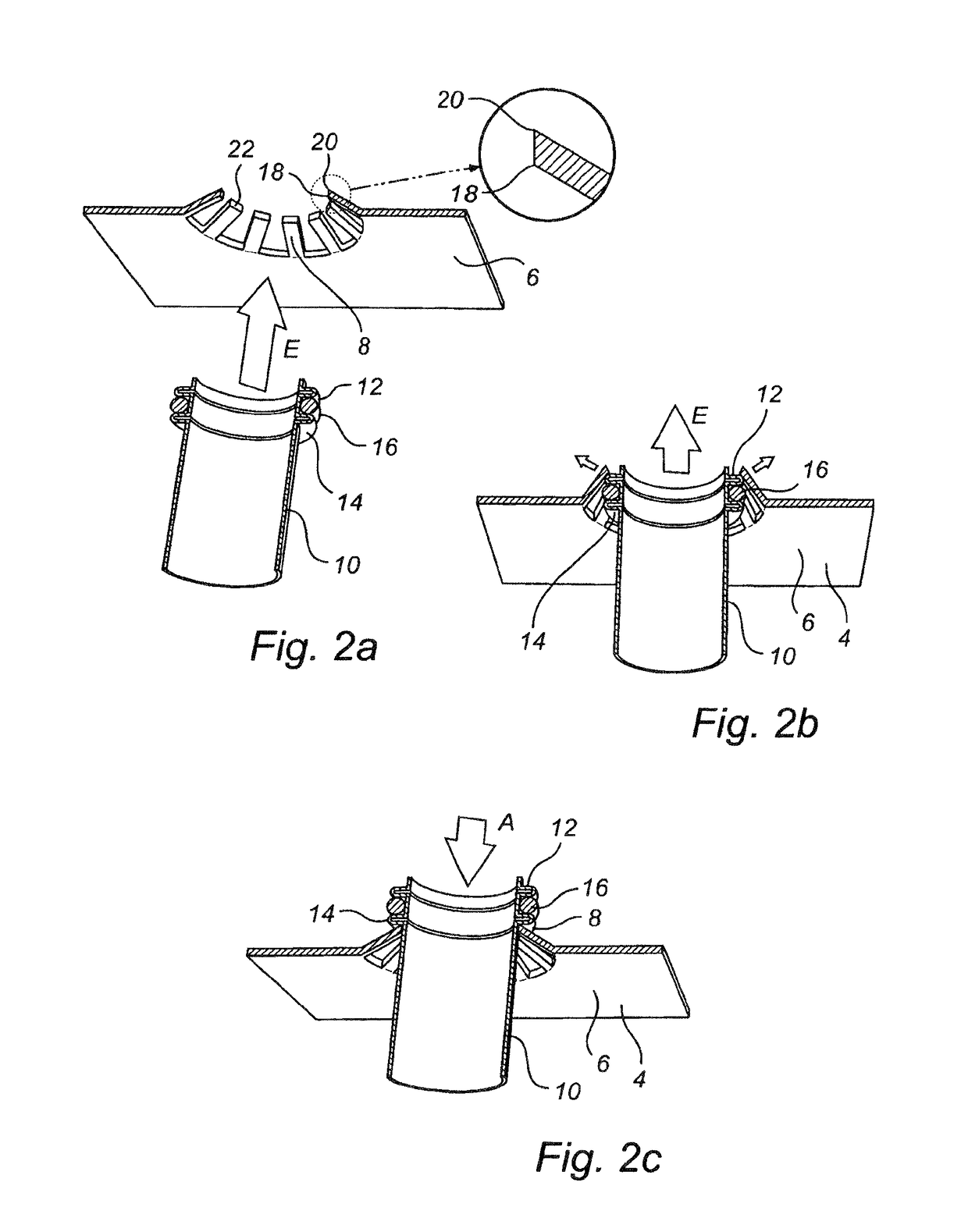
[0042]FIGS. 2a-c illustrates a sequential display of how a fuel conduit 10 is retained in a locking member 4 according to a

[0043]FIG. 2a illustrates the locking member 4 comprising inwardly extending resilient tongues 8. The locking member 4 may e.g. be made of stainless spring steel, spring steel or plastics. The tongues 8 are integrally formed as a one piece extension from the main body 6 of the locking member 4. Each tongue 8 comprises an obtuse edge 18 and an acute edge 20 at the end portion 22 thereof. The angle of the obtuse edge may e.g. be 90°, 100°, 110° or 120° but it is preferably 130° or greater.

[0044]FIG. 2b illustrates a locking member 4 according to the first embodiment wherein a fuel conduit 10 is entered into the locking member 4 in a fuel conduit entering direction E. The external annular beads 12, 14 and the O-ring 16 of the fuel conduit 10 are putting the locking member 4 in an open position for receiving the fuel conduit 10. As seen this is made such that the ex...

second embodiment

[0046]FIGS. 3a-c illustrates a sequential display of how a fuel conduit 10 is retained in a locking member 4 according to a

[0047]FIG. 3a illustrates the locking member 4 comprising inwardly extending resilient tongues 8. The locking member 4 may e.g. be made of stainless spring steel, spring steel or plastics. The tongues 8 are integrally formed as a one piece extension from the main body 6 of the locking member 4. Each tongue 8 comprises an edgeless end portion 22.

[0048]FIG. 3b illustrates a locking member 4 according to the second embodiment wherein a fuel conduit 10 is entered into the locking member 4 in a fuel conduit entering direction E. The external annular beads 12, 14 and the O-ring 16 of the fuel conduit 10 are putting the locking member 4 in an open position for receiving the fuel conduit 10. As seen this is made such that the external annular beads 12, 14 and the O-ring 16 are forcing the tongues 8 to bend outwardly, i.e. the external annular beads 12, 14 and the O-ring...

third embodiment

[0050]FIGS. 4a-c illustrates a sequential display of how a fuel conduit 10 is retained in a locking member 4 according to a

[0051]FIG. 4a illustrates the locking member 4 comprising inwardly extending resilient tongues 8. In the embodiment showed, the main body 6 of the locking member 4 is made of one type of material, e.g. stainless spring steel, spring steel or plastics and the tongues 8 are formed by another type of material having a degree of hardness being less than the degree of hardness of the external annular beads 12, 14 and the O-ring 16 of the fuel conduit 10 A typical O-ring is made of a rubber material having a degree of hardness being in the range 70-80 shore A. By forming the tongues 8 by a type of material having a degree of hardness being less than the degree of hardness of the external annular beads 12, 14 and the O-ring 16 the risk of the tongues 8 to cause any damage to the external annular beads 12, 14 or the O-ring 16 when the fuel conduit 10 is received by the ...


PUM


Abstract

A fuel dispensing unit is provided that includes a fuel conduit including an external annular bead and a locking member including inwardly extending resilient tongues. The locking member is configured to retain the fuel conduit in a locked position and to receive the fuel conduit in an open position. The external annular bead of the fuel conduit causes the locking member to move to the open position when the locking member receives the fuel conduit.

Description

TECHNICAL FIELD OF THE INVENTION[0001]The present invention relates to a fuel dispensing unit comprising a fuel conduit and a locking member for retaining the fuel conduit in a locked position.BACKGROUND OF THE INVENTION[0002]An important part of fuel dispensing units is a fuel conduit for conducting the fuel. Furthermore, it is very important to make sure that all fuel conduits are securely retained in the fuel dispensing unit, this in order to avoid leakage, e.g. due to that two fuel conduits being connected to each other being drawn apart.[0003]Many methods are known for securely retaining a fuel conduit in a fuel dispensing unit. One method aims at welding the fuel conduit to a frame of the fuel dispensing unit. In another method the fuel conduits are attached to the frame of the fuel dispensing unit by bolts or screws. These methods aim at fixedly retaining the fuel conduits in the fuel dispenser unit. A drawback is that it is time consuming to mount the fuel conduits in the fu...

Claims


Application Information

Patent Timeline
Patent Type & Authority Patents(United States)
IPC IPC(8): B67D7/40F16L3/00F16L41/00F16L5/00F16L3/08F16L37/098
CPCF16L3/08B67D7/40F16L3/00F16L5/00F16L37/0985F16L41/00Y10T403/60B67D7/04
Inventor LARSSON, BENGT INGEMARMARTENSSON, MATTIAS GORAN
Owner DOVER FUELING SOLUTIONS UK LTD
Why Eureka
Try Eureka