

Marking Device
a marking device and marking technology, applied in the field of marking devices, can solve problems such as data damage beyond recovery, character erroneous reading, and reading errors
- Summary
- Abstract
- Description
- Claims
- Application Information
AI Technical Summary
Benefits of technology
Problems solved by technology
Method used
Image

Examples
first embodiment
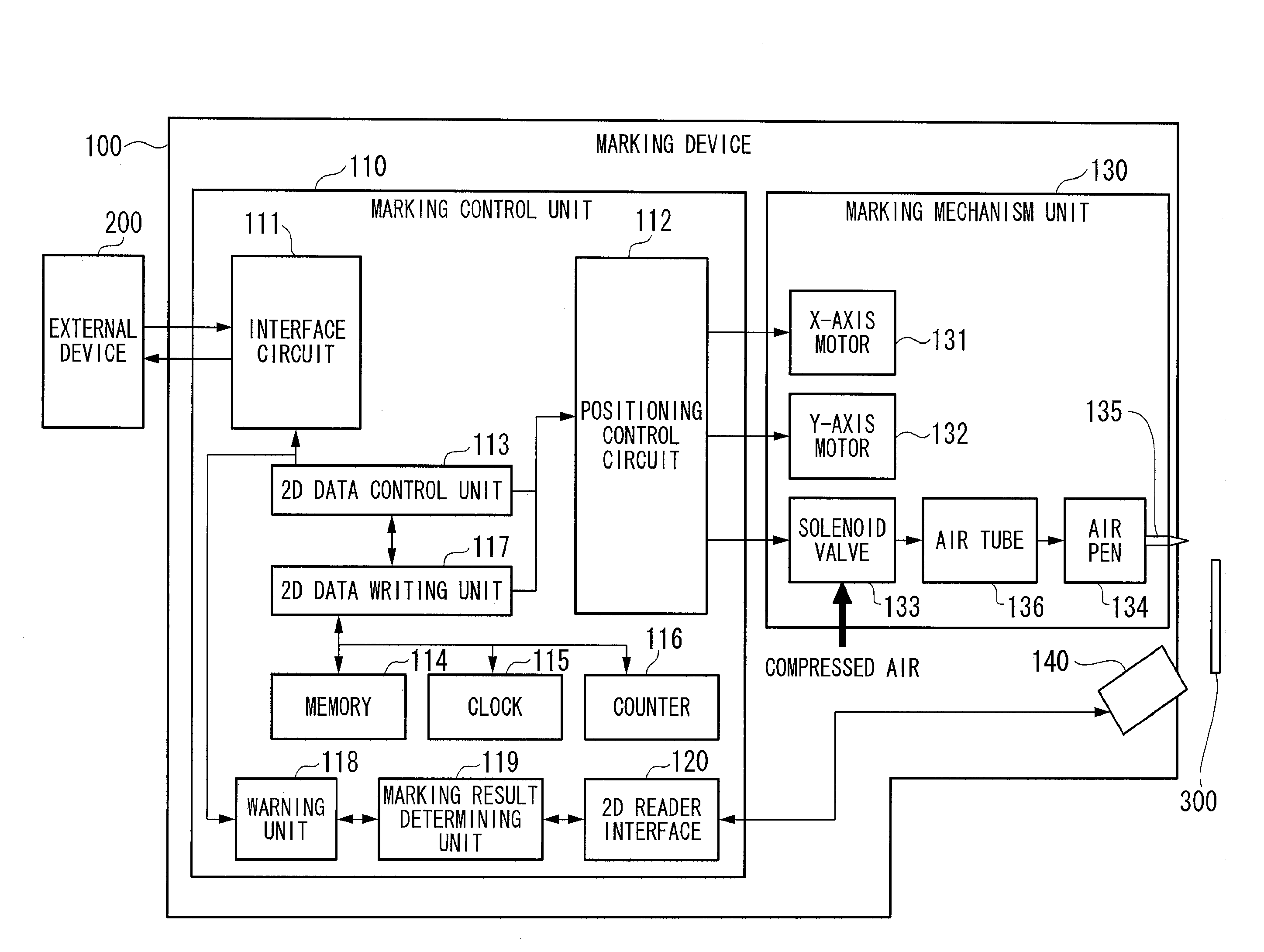
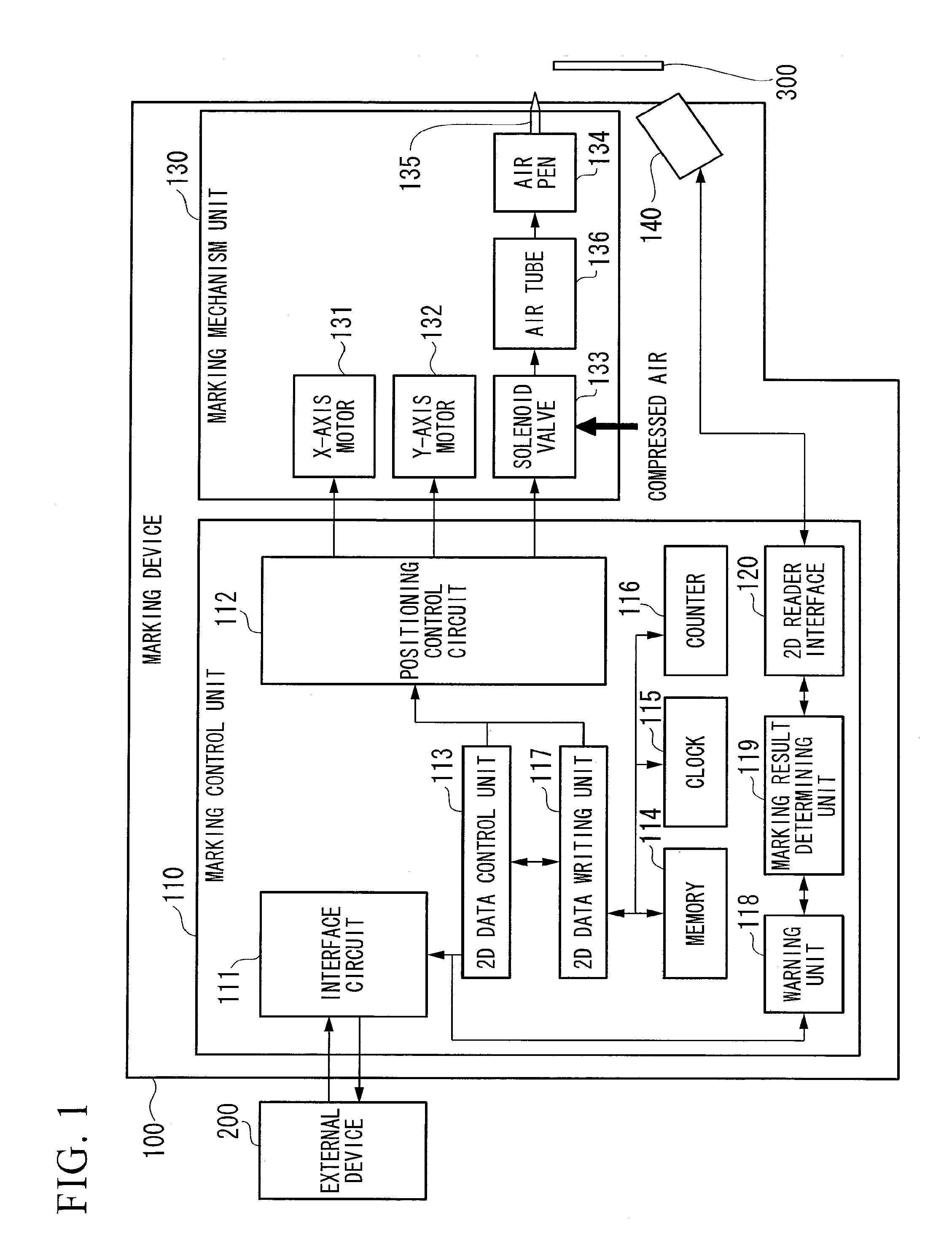
[0091]Hereinafter, a first embodiment of the invention will be described with reference to FIGS. 1 to 7. FIG. 1 is a block diagram showing the configuration of a marking device 100 according to this embodiment. The same elements as those in the marking device 500 of FIG. 10 are represented by the same reference symbols, and descriptions thereof will be omitted.
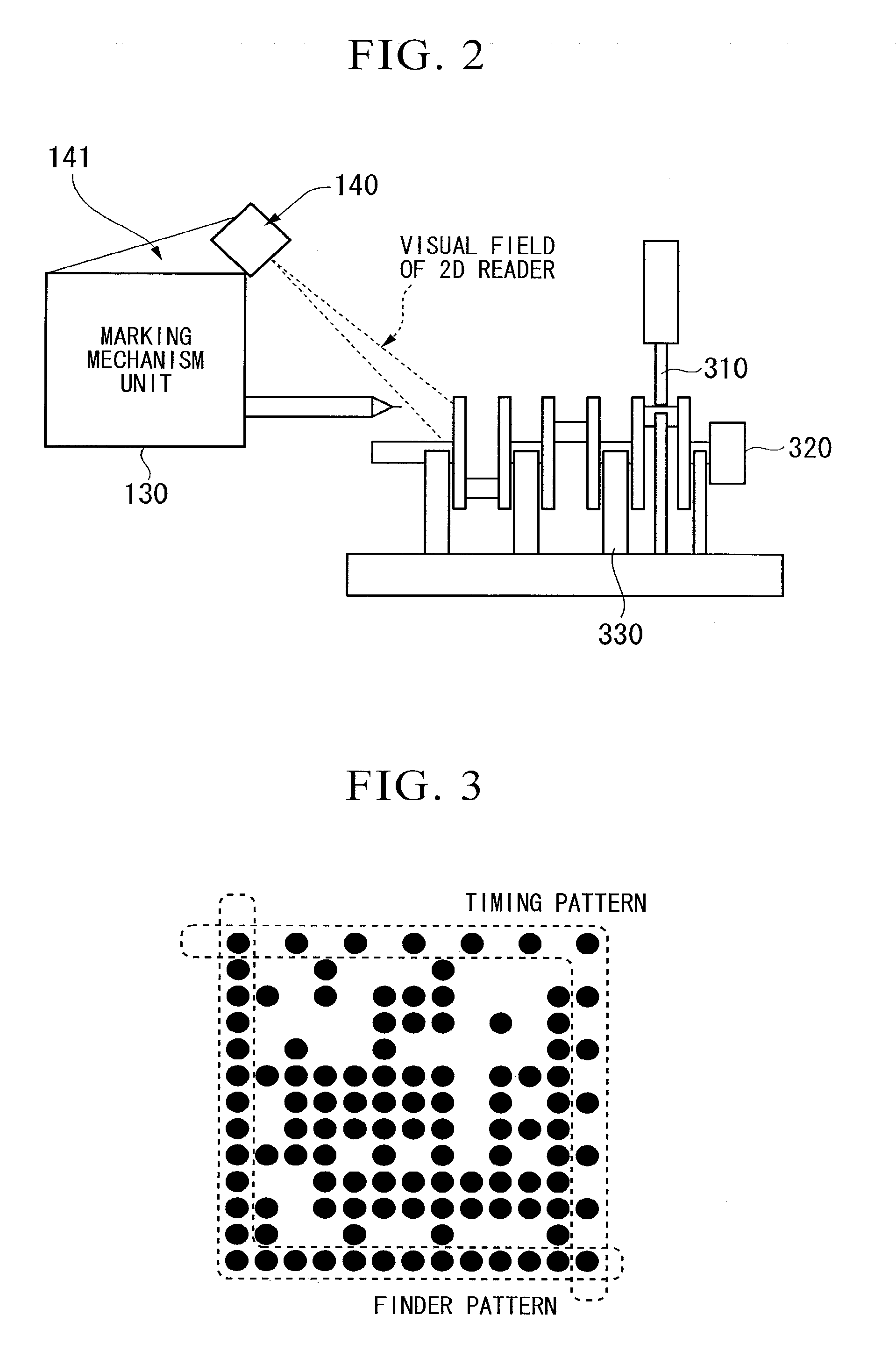
[0092]The marking device 100 includes a 2D reader 140 (a two-dimensional code reading unit). The 2D reader 140 detects bright and dark regions from an engraving result based on a predetermined threshold value. Specifically, the 2D reader 140 irradiates light onto the surface of a marked 2D code by using a light source, and generates 2D code information according to white and black or bright and dark based on the collection result of reflected light by using a lens, and generates character string information as marking information based on the 2D code information in accordance with a predetermined standard.
[0093]The 2D reader 1...
second embodiment
[0129]Next, a second embodiment of the invention will be described with reference to FIG. 8. FIG. 8 is a block diagram showing the configuration of a marking device 201 according to the second embodiment. The marking device 201 of the second embodiment is different from the marking device 100 of the first embodiment in that laser light, not an air pen, is used to form a two-dimensional code on the marking object 300. In FIG. 8, the same elements as those in the marking device 100 of the first embodiment shown in FIG. 1 are represented by the same reference symbols, and descriptions thereof will be omitted.
[0130]The marking device 201 includes, as a two-dimensional code forming unit, a marking control unit 211 and a marking mechanism unit 231, and can perform information communication with the external device 200.
[0131]The marking control unit 211 is a main control unit of the marking device 201, and includes, for example, an interface circuit unit 111, a positioning control circuit ...
third embodiment
[0138]Next, a third embodiment of the invention will be described with reference to FIG. 9. FIG. 9 is a block diagram showing the configuration of a marking device 301 according to the third embodiment. The marking device 301 of the third embodiment is different from the marking device 100 of the first embodiment in that an ink-jet process, not an air pen, is used to form a two-dimensional code on the marking object 300. In FIG. 9, the same elements as those in the marking device 100 of the first embodiment shown in FIG. 1 are represented by the same reference symbols, and descriptions thereof will be omitted.
[0139]The marking device 301 includes, as a two-dimensional code forming unit, a marking control unit 311 and a marking mechanism unit 331, and can perform information communication with the external device 200.
[0140]The marking control unit 311 is a main control unit of the marking device 301, and includes, for example, an interface circuit unit 111, a positioning control circ...
PUM
 Abstract
Description
Claims
Application Information