Toothed rack or threaded rod

a technology of threaded rods and racks, which is applied in the direction of toothed gearings, power driven steering, portable lifting, etc., can solve the problems of production expenditures and restrictions with respect to the implementation of parts to be connected, and achieve the effect of facilitating production

Inactive Publication Date: 2010-03-04
THYSSENKRUPP PRESTA AG
View PDF7 Cites 10 Cited by
  • Summary
  • Abstract
  • Description
  • Claims
  • Application Information

AI Technical Summary

Benefits of technology

[0010]The invention addresses the problem of providing a toothed rack or threaded rod of the above described type which is simple and advantageous in production. This is achieved according to the invention through a toothed rack or threaded rod comprising
[0014]In a toothed rack or threaded rod according to the invention, which in particular represents a threaded gearing member, the connection of the first with the second rod-shaped part is completed via an additional connection part, which includes first and second connection pin, each of which is held by press fit in a hollow volume of the particular rod-shaped part. Consequently, the rod-shaped parts themselves do not need to be implemented with a connection pin but rather, they can have a hollow volume continuous over their length, thus they can be implemented in the form of tubes. Thereby the rod-shaped parts can be implemented in especially simple and advantageous form. Through the press fit of the connection part with the particular rod-shaped part a reliable connection between the first and the second rod-shaped part can be attained. After testing under operating conditions, it was found that herein the loadings occurring in a toothed rack or threaded rod, in particular for a steering mechanism for a motor vehicle, can be transmitted reliably and sustainably.
[0022]Before the forming production of the material elevations the inner diameter of the cylindrically implemented hollow volume is advantageously minimally greater than the outer diameter of the cylinder shell-shaped connection pin, such that both parts could be slid one into the other with minimal play, wherein only through the diameter enlargement or diameter reduction, respectively, entailed in the generation of the material elevations, in at least one of the two parts, the partial coverage necessary for the interference fit is obtained. It becomes thereby possible to compensate form, dimension and position discrepancies of the cylindrical inner form of the hollow volume and of the cylindrical shell surface of the connection pin. Further, the orientation of the parts to be jointed with respect to each other is simplified. The connection is additionally with advantage so laid out that a widening of the outer diameter of the region of the jointing partner into which the connection pin penetrates, is nearly prevented. The values of the widening of the outer diameter should herein be below 0.2 mm, especially preferably be below 0.05 mm. This reduces the material volume which must be removed if in the region of the jointing site a constant outer diameter is demanded. This further lowers the cracking risk in the wall of the hollow volume, such that the strength of the connection is ensured. In the case of a noncylindrical formation of the connection pin and of the hollow volume, this applies analogously. The only minimal widening in this case is even more important since nonround circumferential contours tend more readily to a notch effect and cracks can more easily form.

Problems solved by technology

While through this implementation of the toothed rack with the division of the toothed rack into two or several rod-shaped parts having function regions, facilitation and improvement in the production is attained compared to the implementation of the toothed rack in one piece, the described bolted connection, however, also entails disadvantages, inter alia corresponding production expenditures and restrictions with respect to the implementation of the parts to be connected.

Method used


Image

  • Toothed rack or threaded rod
  • Toothed rack or threaded rod
  • Toothed rack or threaded rod

Examples


Embodiment Construction

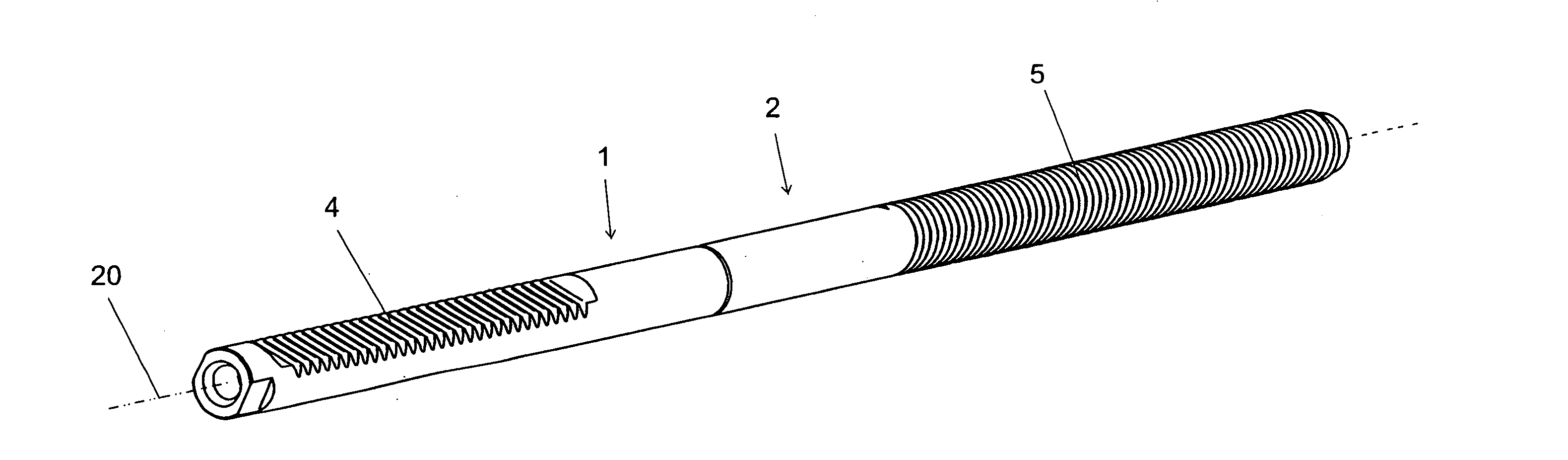
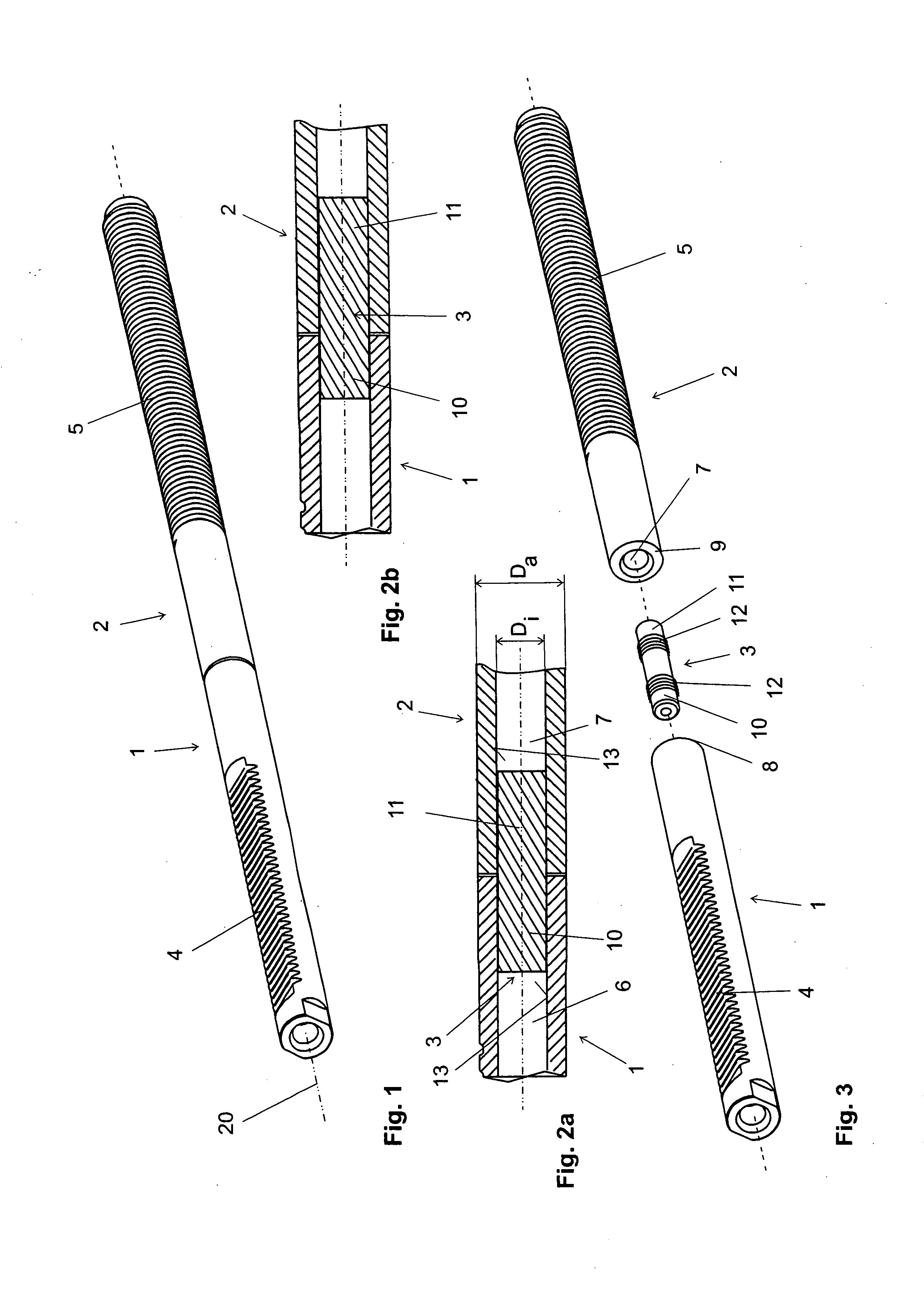
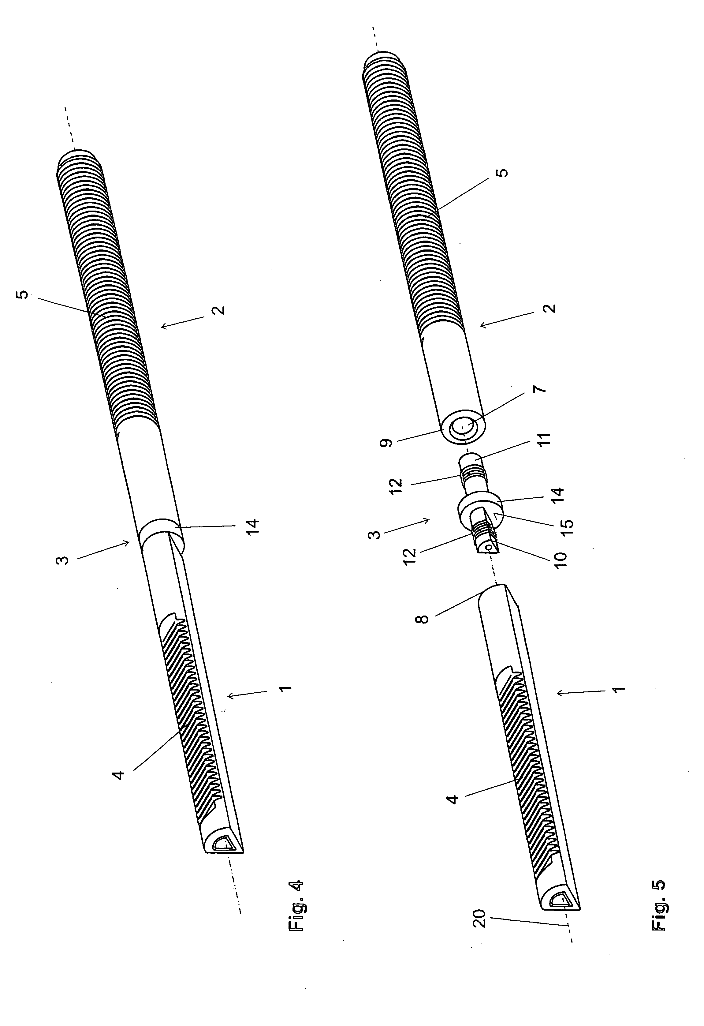
[0036]A first embodiment of a toothed rack according to the invention, for example for application in a steering mechanism of a motor vehicle, will be explained in the following with reference to FIG. 1 to 3. The toothed rack comprises a first and a second rod-shaped part 1, 2 connected with one another by means of a connection part 3. The first and the second rod-shaped part 1, 2 and the connection part 3 have a common longitudinal axis 20 (=the longitudinal axis of the toothed rack). The first rod-shaped part 1 has as a function element the toothing 4 of the toothed rack. The toothing 4 extends over a portion of the entire longitudinal dimension of the toothed rack and this portion of the longitudinal dimension of the toothed rack forms thus a first function region of the toothed rack.

[0037]The second rod-shaped part has as a function element a threading 5, for example for a ball-type threaded drive. This extends over a portion of the entire longitudinal dimension of the toothed r...


PUM


Abstract

The invention relates to a toothed rod or a threaded rod, particularly for a steering device for a motor vehicle, comprising a first rod-shaped pan which has at least one element for converting a rotational movement into a translational movement, said element being the functional element of the toothed rod or threaded rod, and being particularly a teething and / or a threading for engaging in a threaded nut or a threaded mechanism. The invention also has a second rod-shaped part which is connected to the first rod-shaped part and which preferably has at least one additional functional element of the toothed rod or threaded rod. The rod-shaped parts have hollow cavities which open toward connection ends in which connecting pins of a separate connection part are held by a press fit for the purpose of connecting the rod-shaped parts.

Description

[0001]This is a continuation of international application PCT / AT2008 / 000114, filed Mar. 28, 2008, the entire disclosure of which is incorporated herein by reference.BACKGROUND OF THE INVENTION[0002]a) Field of the Invention[0003]The invention relates to a toothed rack or threaded rod, in particular for a steering mechanism for a motor vehicle, which comprises a first rod-shaped part which, as a function element of the toothed rack or threaded rod, comprises at least one element for the conversion of a rotational movement into a translational movement, in particular a toothing and / or threading for the engagement of a threaded nut or of a threaded drive, and a second rod-shaped part which is connected with the first rod-shaped part and which preferably comprises at least one further function element of the toothed rack or of the threaded rod. At least one of the rod-shaped parts comprises a hollow volume opening out at a connection end of the rod-shaped part, and a connection pin is h...

Claims


Application Information

Patent Timeline
Patent Type & Authority Applications(United States)
IPC IPC(8): B62D3/12B62D3/04F16H55/26F16H55/02
CPCB62D3/126B62D5/0427B62D5/0448F16D1/02Y10T74/1967F16D1/0858F16H25/24F16H55/26F16D1/072
Inventor BILMAYER, ROMANECKSTEIN, RALF
Owner THYSSENKRUPP PRESTA AG
Why Eureka
Try Eureka