Frequency detection circuit

a frequency detection and circuit technology, applied in the field of frequency detection circuits, can solve the problems of large electric power consumption, large circuit structure, and large siz

Inactive Publication Date: 2010-03-04
SEMICON COMPONENTS IND LLC
View PDF17 Cites 9 Cited by
  • Summary
  • Abstract
  • Description
  • Claims
  • Application Information

AI Technical Summary

Benefits of technology

[0010]The preferred embodiments of the present invention have been developed in view of the above-mentioned and/or other problems in t

Problems solved by technology

The circuit for detecting a frequency using a conventional F-V converter is equipped with an operation amplifier as explained above, a

Method used


Image

  • Frequency detection circuit
  • Frequency detection circuit
  • Frequency detection circuit

Examples


Embodiment Construction

[0049]In the following paragraphs, some preferred embodiments of the invention will be described by way of example and not limitation. It should be understood based on this disclosure that various other modifications can be made by those in the art based on these illustrated embodiments.

[0050]Hereinafter, an embodiment of the present invention will be explained with reference to the attached drawings.

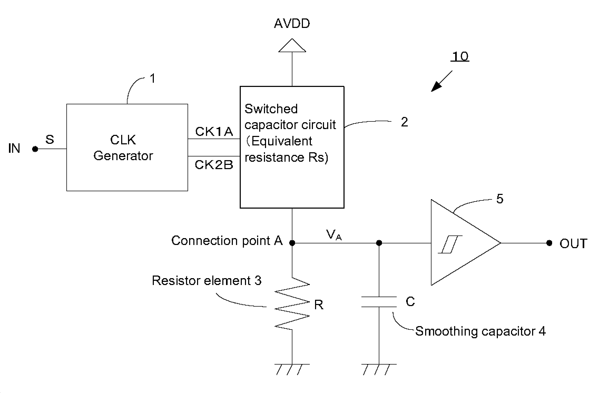
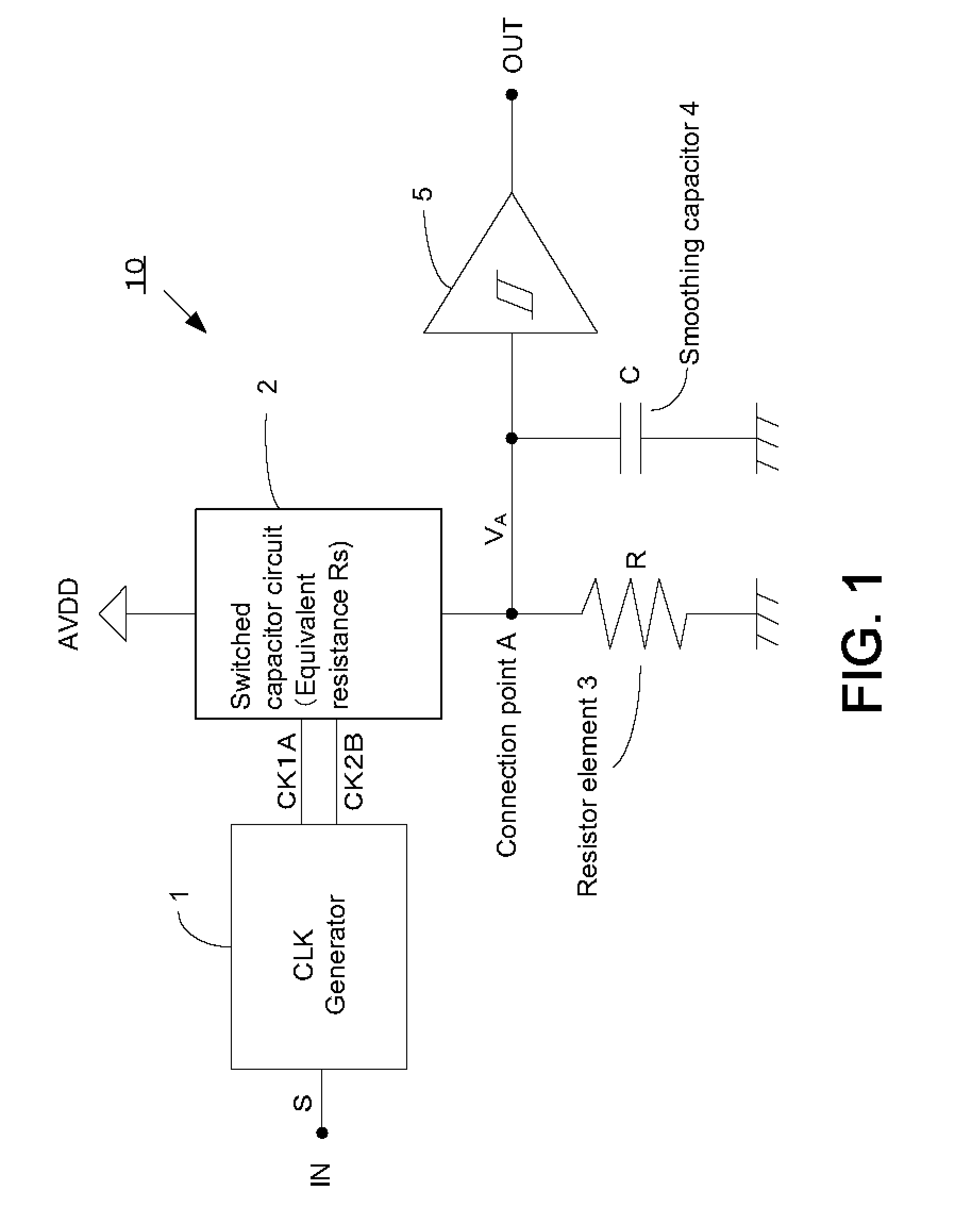
[0051]FIG. 1 shows a schematic block diagram of a frequency detection circuit 10 according to an embodiment of the present invention. This frequency detection circuit 10 is comprised of a clock generator 1, a switched capacitor circuit 2, a resistor element 3, a capacitor 4, and a Schmitt circuit 5. It should be noted that the present invention is not limited to this embodiment and that the embodiment can be arbitrarily modified within the scope of the present invention.

[0052]One end of the switched capacitor circuit 2 is connected to a power supply terminal and a power supply voltage A...


PUM


Abstract

In some preferred embodiments, a switched capacitor circuit configured to change its equivalent resistance depending on the frequency of an input clock signal and a resistor element are connected in series. A power source voltage is divided by the equivalent resistance of the switched capacitor circuit and the resistance of the resistor element, and the divided voltage is inputted to a Schmitt circuit. The Schmitt circuit outputs a high-level signal when the inputted divided voltage is higher than a threshold voltage and a low-level signal when the inputted divided voltage is lower than a threshold voltage. Thus, depending on the frequency of the input clock signal, a high-level signal or a low-level signal is outputted.

Description

[0001]This application claims priority under 35 U.S.C. §119 to Japanese Patent Application No. 2008-203280 filed on Aug. 6, 2008, the entire disclosure of which is incorporated herein by reference in its entirety.BACKGROUND OF THE INVENTION[0002]1. Field of the Invention[0003]The present invention relates to a frequency detection circuit. More specifically it relates to a frequency detection circuit preferably for use in, e.g., a sleeve circuit for LSIs with no standby terminal and configured to output a high-level signal or a low-level signal when a frequency of an input clock signal is higher or lower than a pre-set frequency, respectively.[0004]2. Description of the Related Art[0005]The following description sets forth the inventor's knowledge of related art and problems therein and should not be construed as an admission of knowledge in the prior art.[0006]For example, in some sleeve circuits for LSIs with no standby terminal, the circuit is configured to output a low-level sign...

Claims


Application Information

Patent Timeline
IPC IPC(8): H03K5/26
CPCH03K5/26G01R23/06G01R19/165G01R19/252
Inventor TOKANO, TAKASHI
Owner SEMICON COMPONENTS IND LLC
Why Eureka
Try Eureka