Scanner device

Active Publication Date: 2010-03-04
PFU LTD
View PDF16 Cites 48 Cited by
  • Summary
  • Abstract
  • Description
  • Claims
  • Application Information

AI Technical Summary

Benefits of technology

[0016]According to the present invention, it is sufficient to combine the lengths of the front surface cover and the upper surface cover to secure the necessary length for a document ejection tray. Accordingly, even if the height of the front surface portion is lo

Problems solved by technology

This causes constraints in design.
However, in this case, the

Method used


Image

  • Scanner device
  • Scanner device
  • Scanner device

Examples


Embodiment Construction

[0027]Preferred embodiments of a scanner device according to the present invention will be described below with reference to the accompanying drawings.

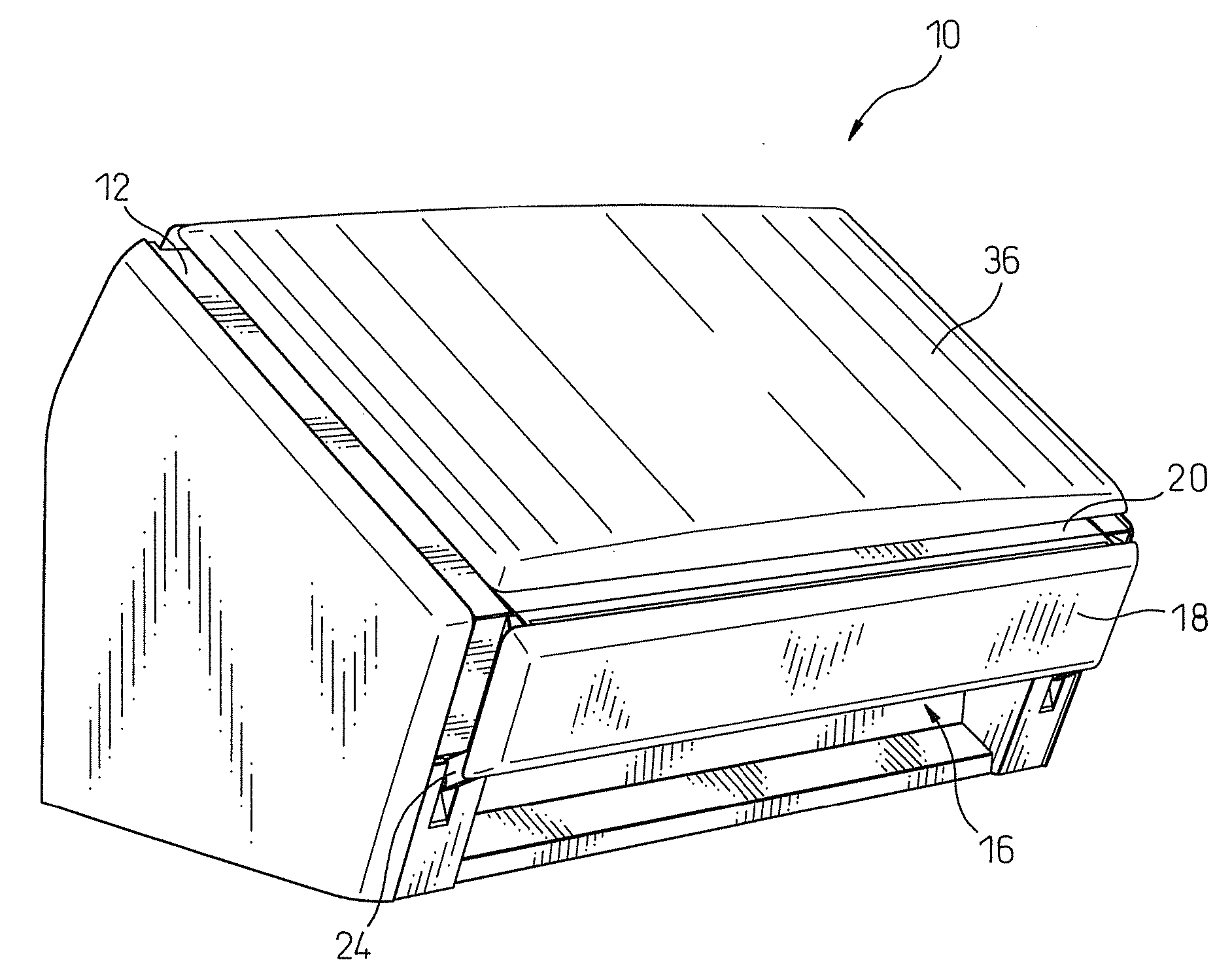
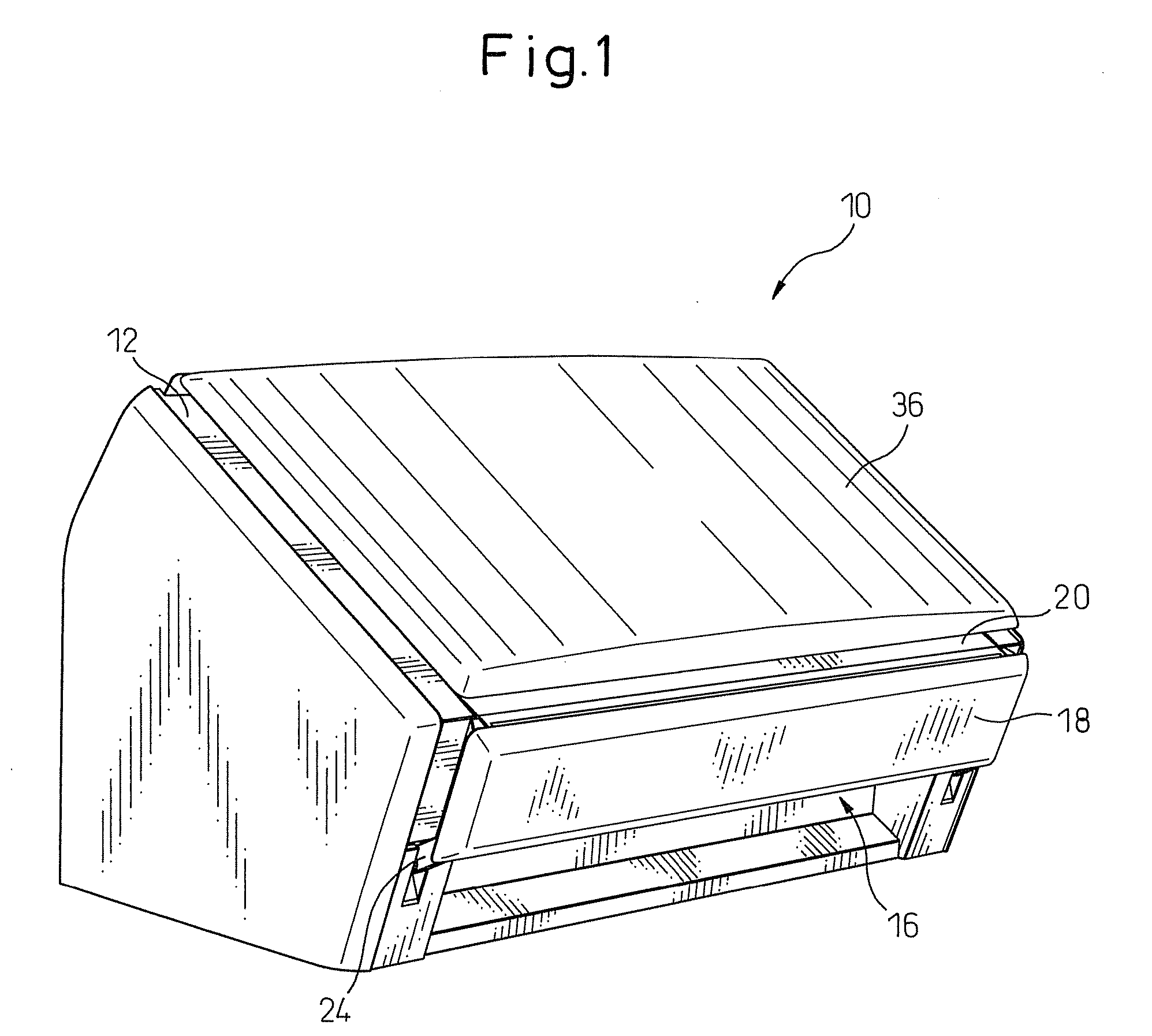
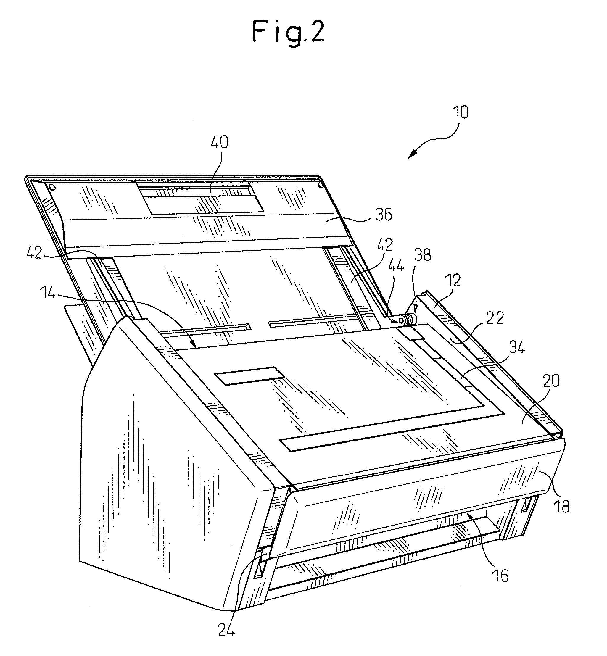
[0028]First, referring to FIGS. 1 to 7, a scanner device 10 according to a first embodiment of the present invention will be described. Scanner device 10 is a desktop type designed for use on the top of an office desk or the like and includes a generally pentagonal prism-shaped scanner body 12 having a pentagonal side surface. A document insertion opening 14 is formed at the upper rear part of scanner body 12, while a document ejection opening 16 is formed at the lower front part of scanner body 12. A document taken in from document insertion opening 14 is read and then ejected from document ejection opening 16.

[0029]Further, scanner device 10 includes a front surface cover 18 covering the front surface of scanner body 12 and an upper surface cover 20 covering the upper surface of scanner body 12.

[0030]Front surface cover 18 is arrang...


PUM


Abstract

A scanner device includes a scanner body formed with a document insertion opening and a document ejection opening and is configured so that an document taken in from the document insertion opening is read and then ejected from the document ejection opening. The scanner device further includes an upper surface cover covering the upper surface of the scanner body and a front surface cover covering the front surface of the scanner body. The front cover is connected at a lower end side thereof to the lower front part of the scanner body and connected at an upper end side thereof to pivotably connected to the front end side of the upper surface cover. By opening the front surface cover from the front surface of the scanner body, the upper surface cover and front surface cover form a document ejection tray.

Description

CROSS REFERENCE TO RELATED APPLICATION[0001]The present invention contains subject matter related to Japanese Patent Application No. 2008-226101, filed in the Japan Patent Office on Sep. 3, 2008, the entire contents of which being incorporated herein by reference.BACKGROUND OF THE INVENTION[0002]1. Field of the Invention[0003]The present invention relates to a scanner device configured so that a cover attached pivotably to a scanner body functions as a document ejection tray.[0004]2. Description of the Related Art[0005]A scanner device includes a document insertion opening and a document ejection opening and is configured to read a document inserted from the document insertion opening and then eject the document from the document ejection opening. The scanner device further includes a document feed tray for placing a stock of documents thereon and a document ejection tray for receiving ejected documents and is configured so as to be able to successively feed the topmost documents of...

Claims


Application Information

Patent Timeline
IPC IPC(8): H04N1/04
CPCH04N1/00525H04N1/00535H04N2201/0081H04N1/00631H04N1/12H04N1/00554
Inventor YOSHIDA, SHOJISHIBATA, HIDEAKIMATSUDA, YASUHIROYAMASHITA, MASAAKI
Owner PFU LTD
Why Eureka
Try Eureka