Rear-Installable Fiber Optic Modules and Equipment

Active Publication Date: 2010-03-04
CORNING OPTICAL COMM LLC
View PDF101 Cites 96 Cited by
  • Summary
  • Abstract
  • Description
  • Claims
  • Application Information

AI Technical Summary

Benefits of technology

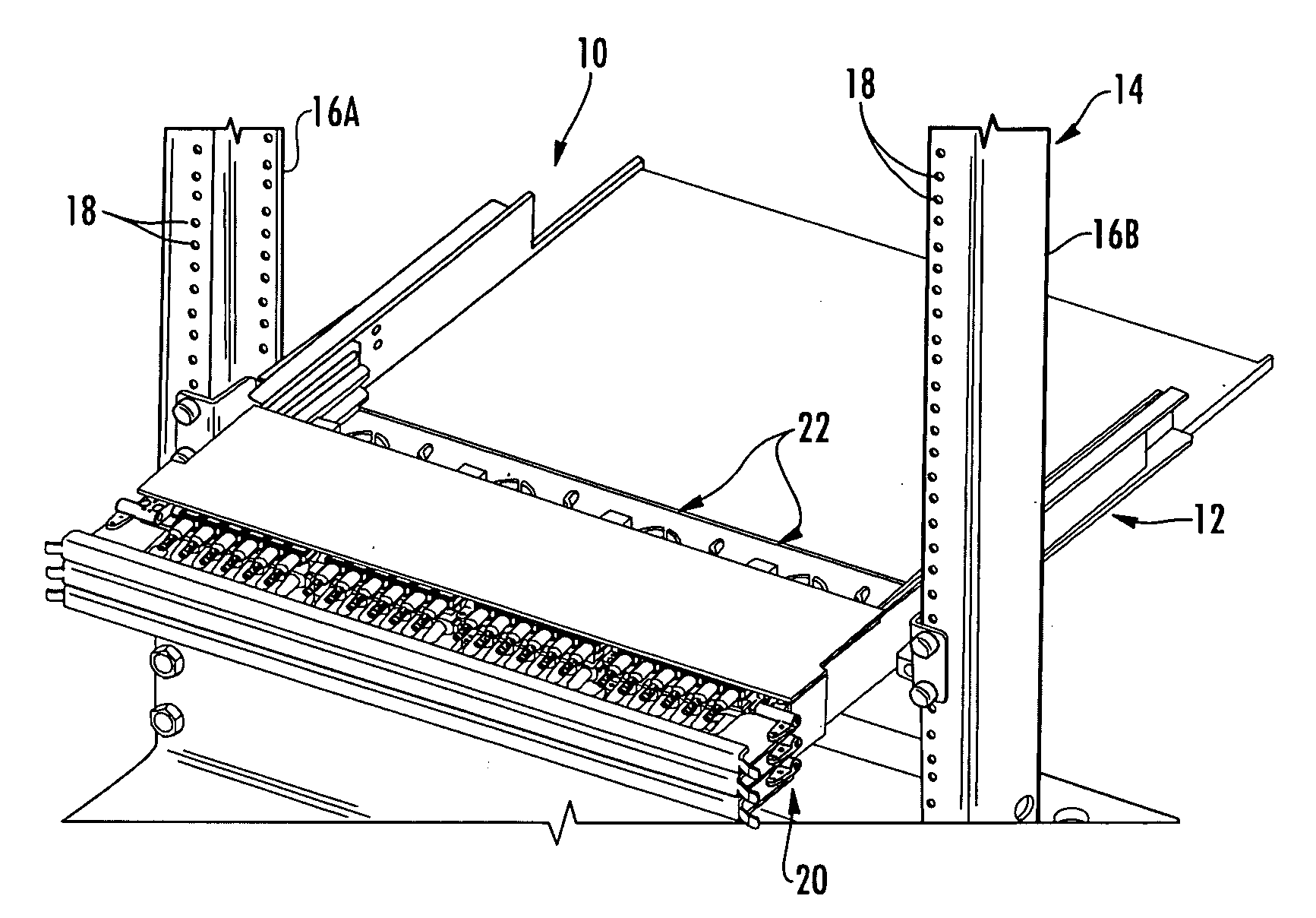
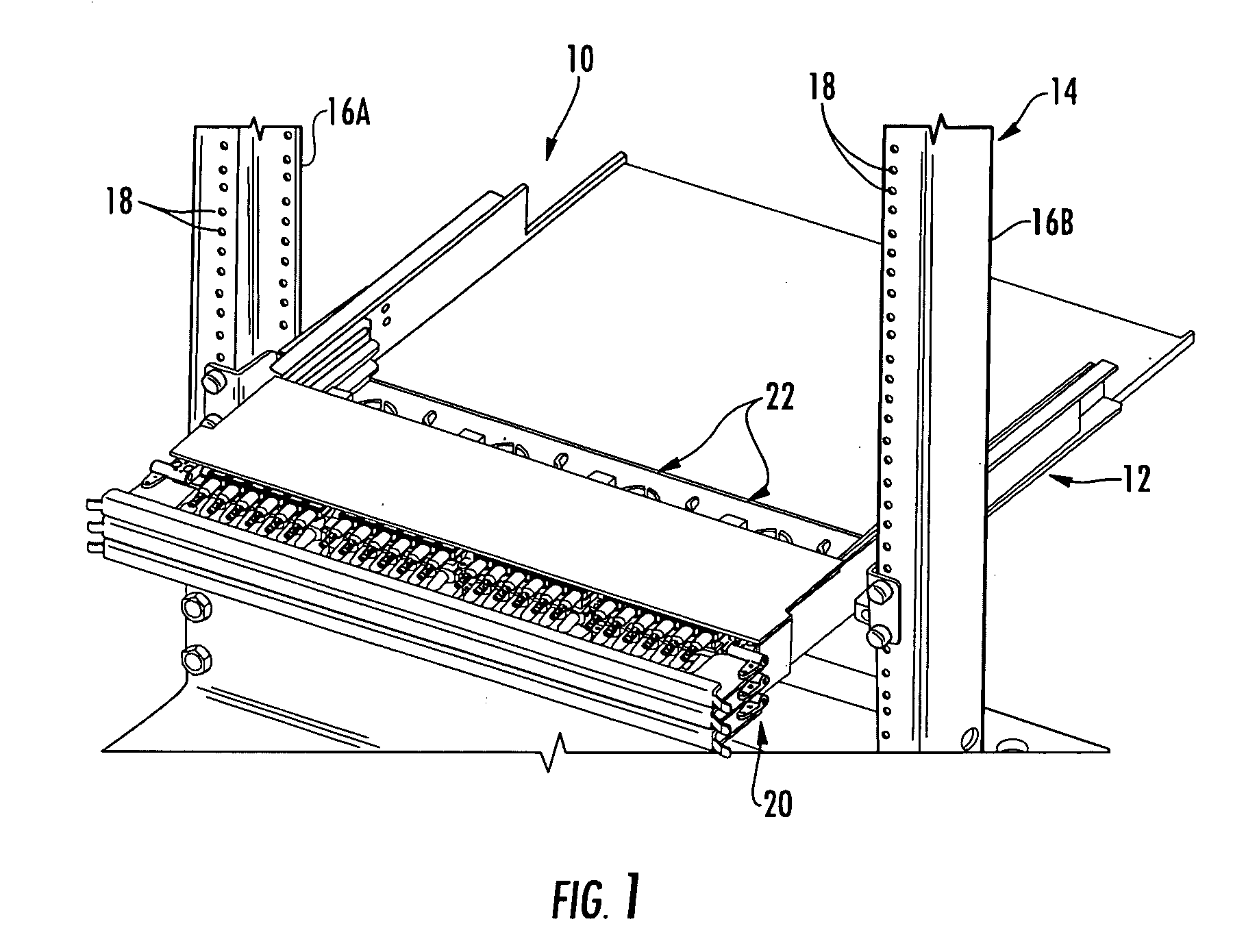
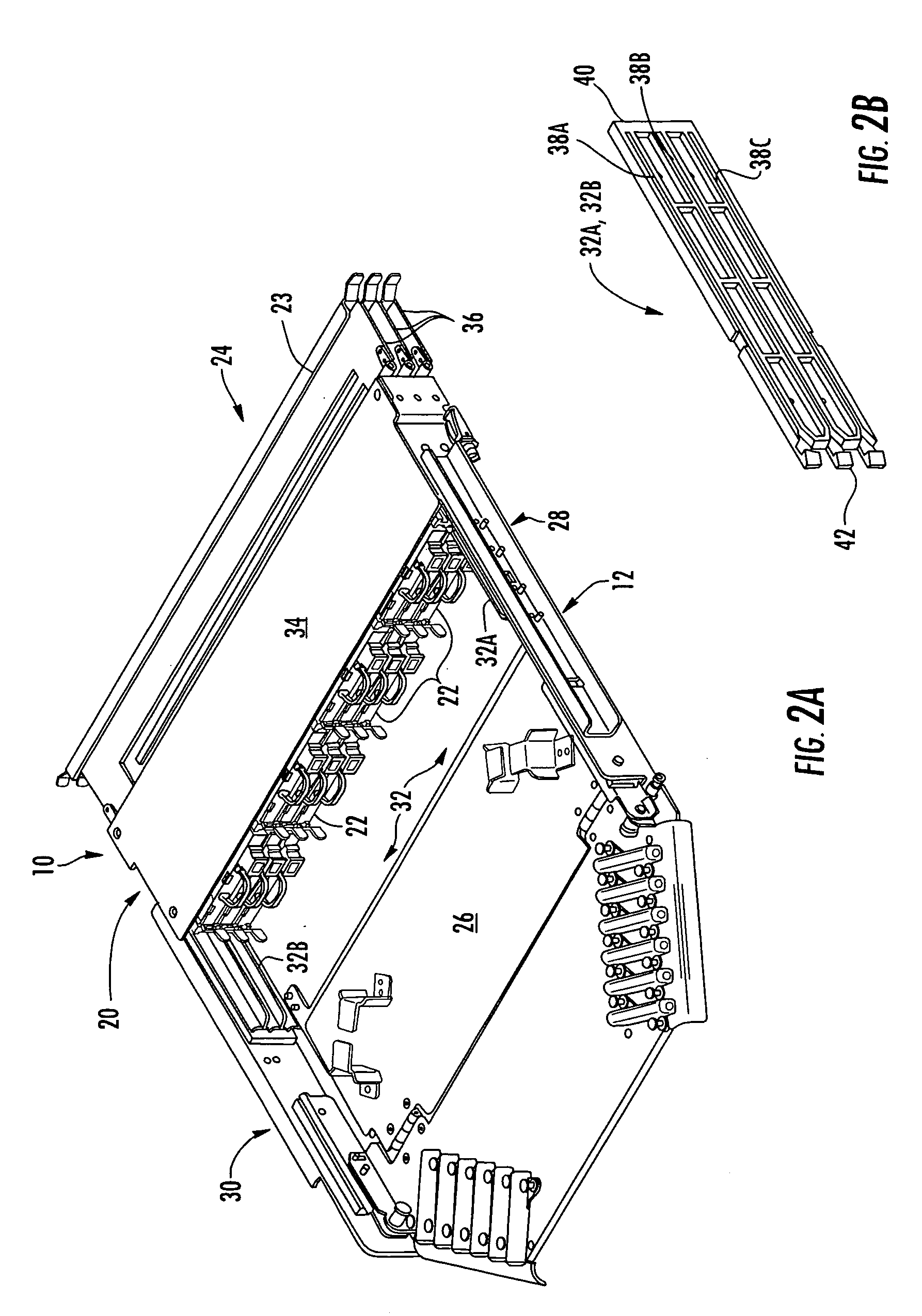
[0011]Embodiments disclosed in the detailed description include fiber optic equipment that supports one or more rear-installable fiber optic modules. The fiber optic modules are configured to support fiber optic connections. The fiber optic equipment is comprised of a chassis defining a front end and a rear section. At least one guide system is disposed in the chassis and configured to receive at least one fiber optic module. The guide system may be provided

Problems solved by technology

Even with advancements in access to fiber optic modules, the labor associated with installing fiber optic modules and making optical connections is significant.
Because data distribution centers are typically large facilities with significant numbers of equipment racks, walking back and forth from the rear section

Method used


Image

  • Rear-Installable Fiber Optic Modules and Equipment
  • Rear-Installable Fiber Optic Modules and Equipment
  • Rear-Installable Fiber Optic Modules and Equipment

Examples


Example

[0054]Reference will now be made in detail to the preferred embodiments of the present invention, examples of which are illustrated in the accompanying drawings, in which some, but not all embodiments of the invention are shown. Indeed, the invention may be embodied in many different forms and should not be construed as limited to the embodiments set forth herein; rather, these embodiments are provided so that this disclosure will satisfy applicable legal requirements. Whenever possible, like reference numbers will be used to refer to like components or parts.

[0055]Embodiments disclosed in the detailed description include fiber optic equipment that supports one or more rear-installable fiber optic modules. The fiber optic modules are configured to support fiber optic connections. The fiber optic equipment is comprised of a chassis defining a front end and a rear section. At least one guide system is disposed in the chassis and configured to receive at least one fiber optic module. T...


PUM


Abstract

Fiber optic equipment that supports one or more rear-installable fiber optic modules is disclosed. The fiber optic equipment is comprised of a chassis defining a front end and a rear section. At least one guide system is disposed in the chassis and configured to receive at least one fiber optic module. The guide system may be provided in the form of a rail guide system. The at least one guide system receives the at least one fiber optic module from the rear section on the chassis and is configured to guide the fiber optic module toward the front end of the chassis. In this manner, a technician can make fiber optic connections to fiber optic modules and also install the fiber optic modules into the fiber optic equipment from the rear section of the chassis to reduce time and/or labor in making fiber optic connections.

Description

RELATED APPLICATIONS[0001]The present application claims priority to U.S. Provisional Patent Application Ser. No. 61 / 190,538 filed Aug. 29, 2008, entitled “High Density Data Center Hardware, Assemblies and Components,” which is incorporated herein by reference in its entirety.[0002]The present application also claims priority to U.S. Provisional Patent Application Ser. No. 61 / 197,068 filed Oct. 23, 2008, entitled “High Density Data Center Hardware, Assemblies and Components,” which is incorporated herein by reference in its entirety.[0003]The present application is related to co-pending U.S. patent application Ser. No. ______, entitled “Independently Translatable Modules and Fiber Optic Equipment Trays In Fiber Optic Equipment” which is incorporated herein by reference in its entirety.[0004]The present application is related to co-pending U.S. patent application Ser. No. ______, entitled “Rear-Slidable Extension in Fiber Optic Equipment Tray” which is incorporated herein by referenc...

Claims


Application Information

Patent Timeline
IPC IPC(8): G02B6/00
CPCG02B6/3897G02B6/4455G02B6/4452G02B6/4471G02B6/4453
Inventor COOKE, TERRY L.KLAVUHN, TORY A.DEAN, JR., DAVID L.GARCIA, JUANMARIANO, ELMERLOPEZ, MANUELGONZALEZ, JUAN MIGUEL
Owner CORNING OPTICAL COMM LLC
Why Eureka
Try Eureka