
Compact drive for compressor variable diffuser

a compressor and variable technology, applied in the direction of machines/engines, reaction engines, liquid fuel engines, etc., can solve the problems of inability to achieve the desired accuracy, large drive motors, complex mechanical drive arrangement in the prior art,

Active Publication Date: 2010-03-04
HAMILTON SUNDSTRAND CORP
View PDF24 Cites 4 Cited by
  • Summary
  • Abstract
  • Description
  • Claims
  • Application Information

AI Technical Summary

Problems solved by technology

The prior art mechanical drive arrangement is complex, requires a r

Method used


Image

  • Compact drive for compressor variable diffuser
  • Compact drive for compressor variable diffuser
  • Compact drive for compressor variable diffuser

Examples


Embodiment Construction

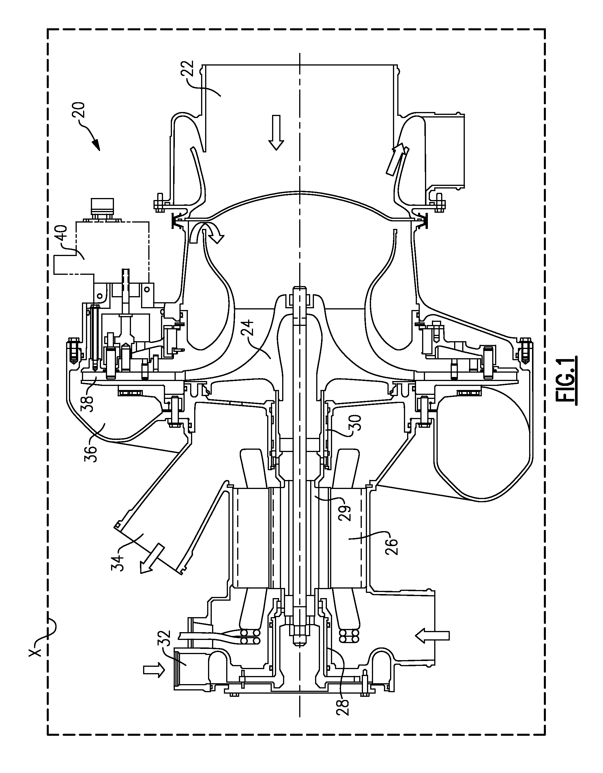
[0011]A compressor 20 is illustrated in FIG. 1, and may be mounted in an aircraft X, shown schematically. An inlet 22 delivers air to be compressed to a compressor impeller 24. An electric motor 26 drives the impeller 24. Air bearings 28 and 30 support the motor shaft 29 for rotation. Cooling air 32 is delivered to the air bearings from a source 34. An outlet 36 of the compressor is positioned downstream of the impeller. A diffuser 38 has a plurality of vanes (see FIG. 4) which can be pivoted to control the cross-sectional flow area. A motor 40 drives the diffuser as will be explained below.

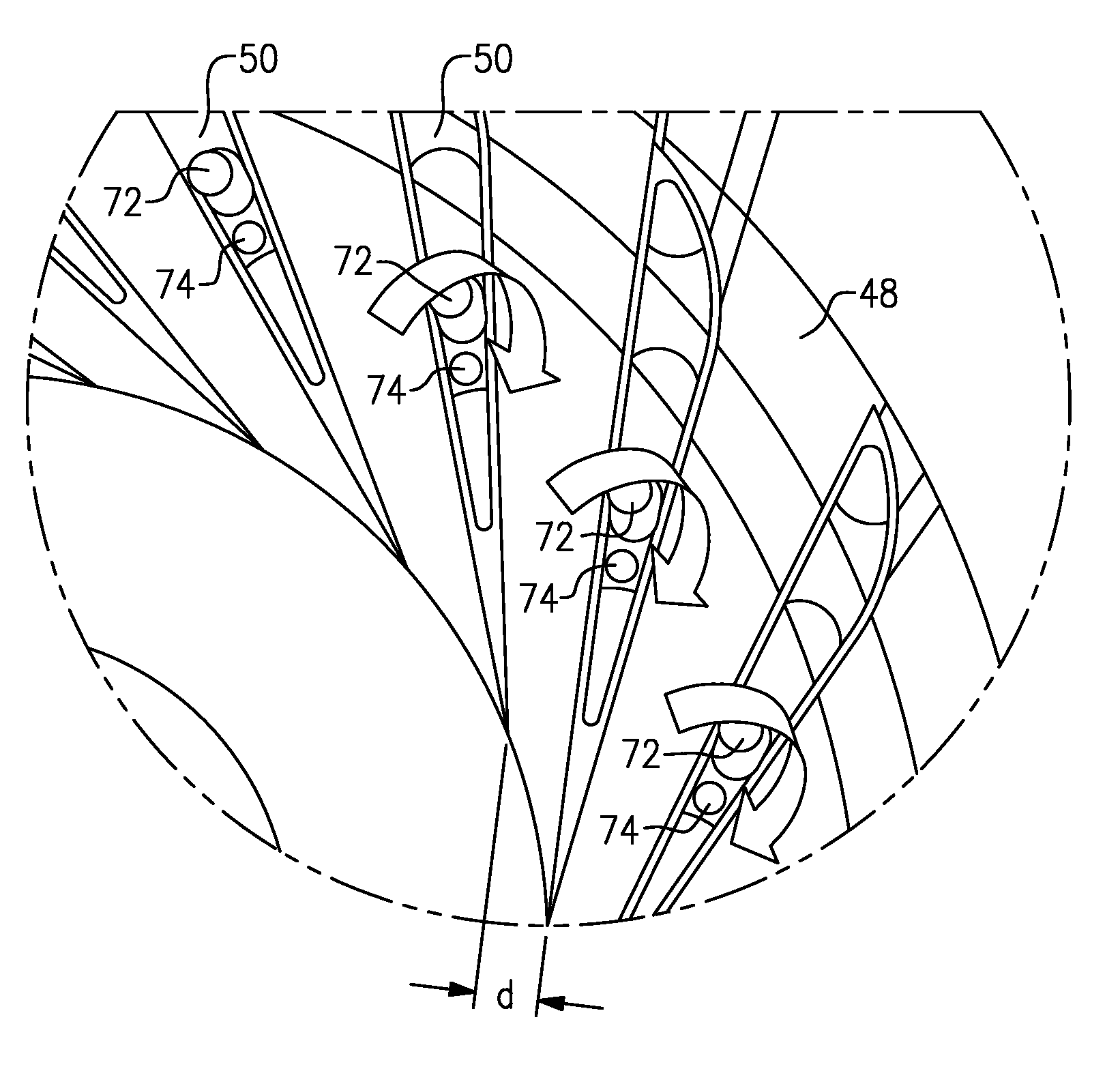
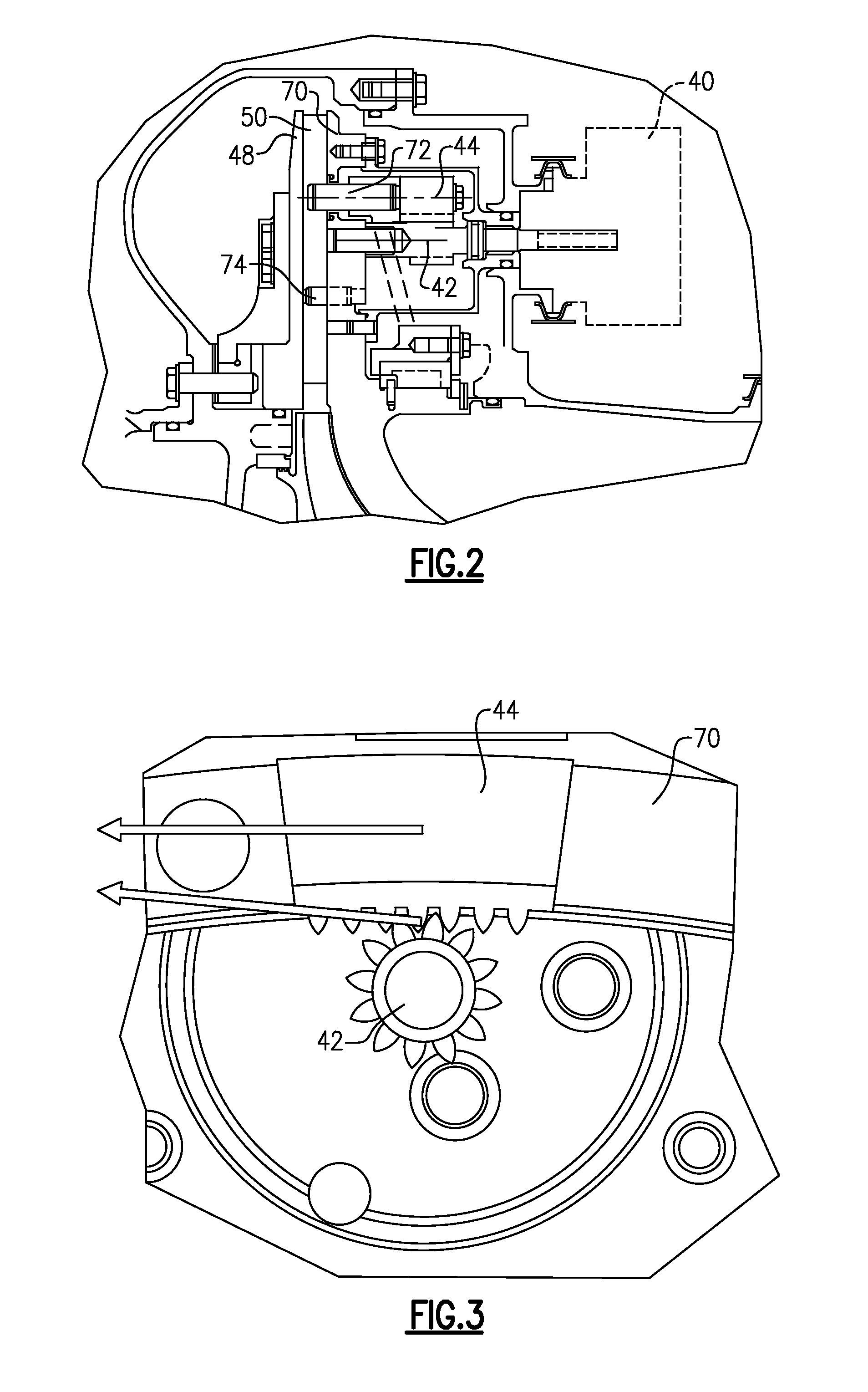
[0012]As shown in FIG. 2, the motor 40 drives a pinion gear 42 that has teeth engaged with teeth on a curved rack section 44. As the pinion gear 42 rotates, it causes the curved rack section 44 to rotate. The curved rack section 44 drives a ring 70. Ring 70 carries pins 72. Pins 72, when rotated, cause diffuser vanes 50 to pivot relative to housing 48 on pins 74. As the diffuser vanes 50 pivot, t...


PUM


Abstract

A compressor has an impeller and an inlet delivering air to the impeller. A variable diffuser is positioned downstream of the impeller and includes a plurality of pivoting vanes. A drive arrangement pivots the vanes, and includes an electric motor causing a pinion gear to rotate. The pinion gear has gear teeth engaging gear teeth on a rack section. Rotation of the rack section causes the vanes to pivot.

Description

BACKGROUND OF THE INVENTION[0001]This application relates to a drive for a compressor diffuser.[0002]Diffusers are utilized to control an outlet cross-sectional flow area in a compressor. Variable diffusers include a plurality of vanes that can be pivoted to change the cross-sectional flow area between minimum and maximum amounts.[0003]In one recently developed diffuser, disclosed in U.S. patent application Ser. No. 11 / 108,286, a ring is driven by a mechanical connection to rotate. When the ring rotates, it carries pins that are received within diffuser vanes. The diffuser vanes pivot as the ring rotates, and thus the cross-sectional flow area can be controlled.[0004]The prior art mechanical drive arrangement is complex, requires a relatively large drive motor, and may not be as accurate as desired.SUMMARY OF THE INVENTION[0005]In a disclosed embodiment of this invention, a drive arrangement for driving diffuser vanes includes an electric motor driving a pinion gear. The pinion gear...

Claims


Application Information

Patent Timeline
IPC IPC(8): F04D29/56
CPCF04D25/06F04D29/462F04D27/0246F04D25/08F05D2250/52
Inventor BEERS, CRAIG M.BECK, JOHN M.
Owner HAMILTON SUNDSTRAND CORP
Features
  • Generate Ideas
  • Intellectual Property
  • Life Sciences
  • Materials
  • Tech Scout
  • Unparalleled Data Quality
  • Higher Quality Content
  • 60% Fewer Hallucinations
Learn More