

Iron
- Summary
- Abstract
- Description
- Claims
- Application Information
AI Technical Summary
Benefits of technology
Problems solved by technology
Method used
Image

Examples
first embodiment
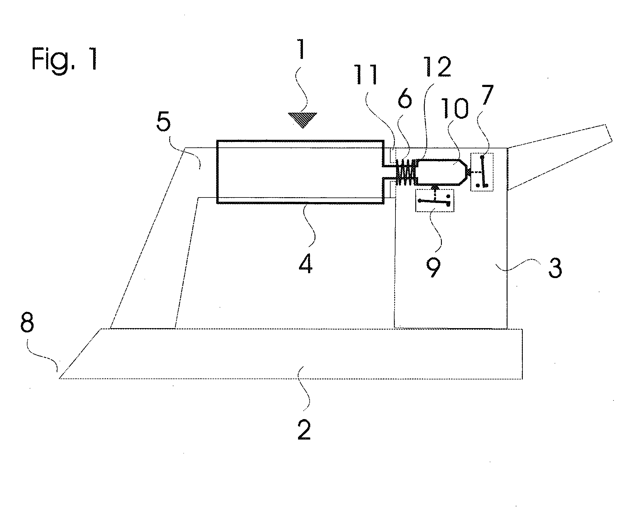
[0036]FIG. 1 schematically describes an iron according to the invention; and
second embodiment
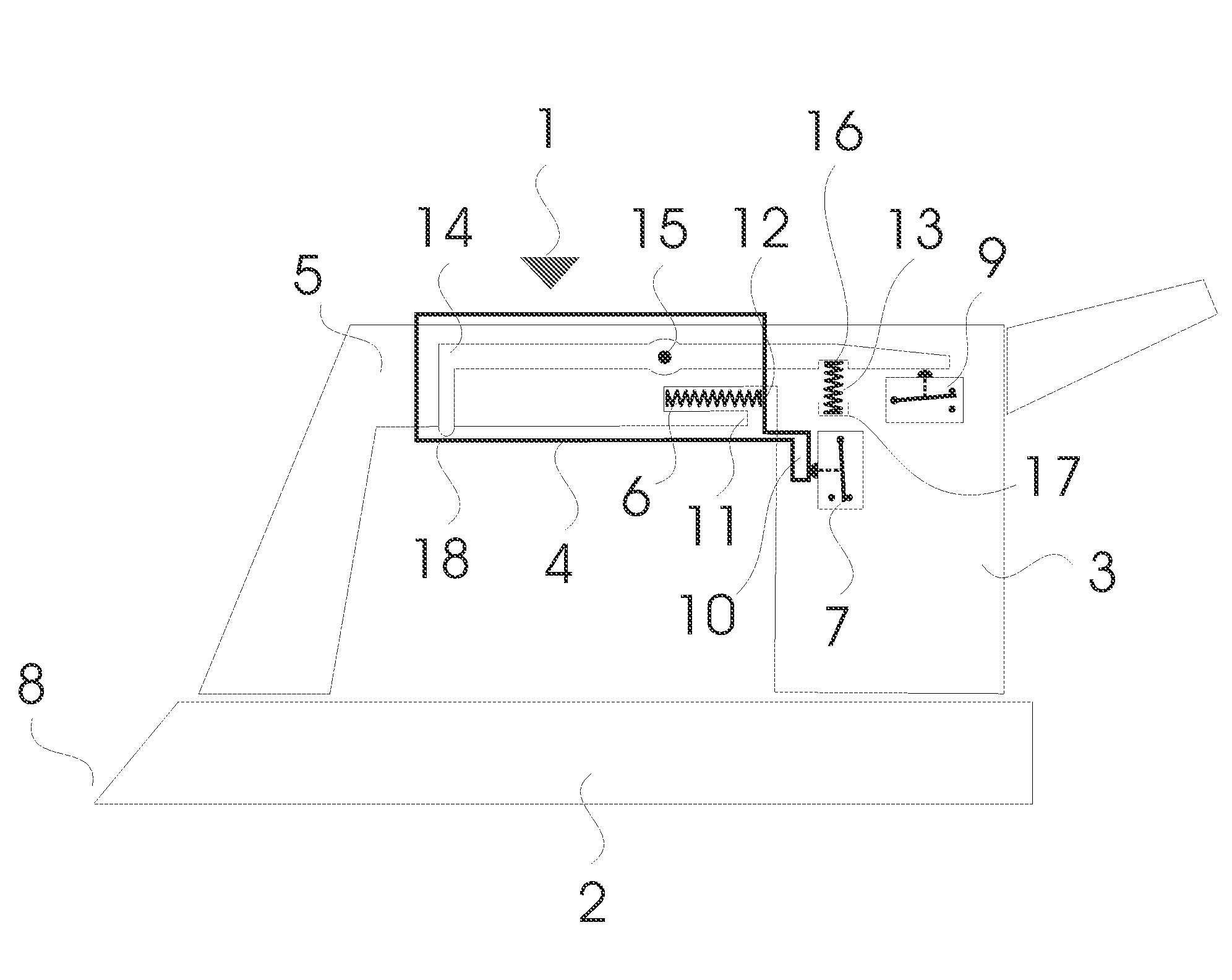
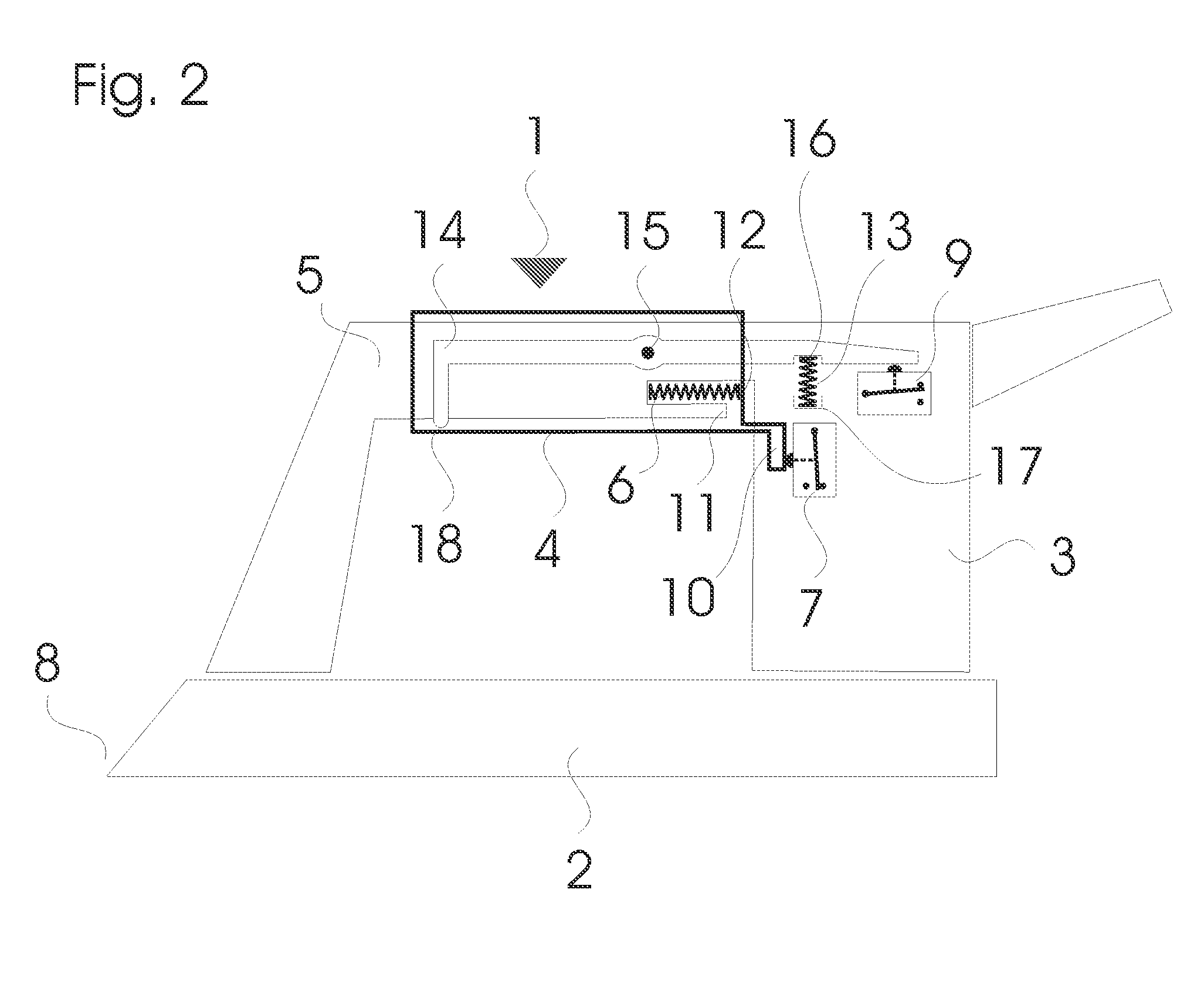
[0037]FIG. 2 schematically describes an iron according to the invention.
[0038]The iron 1 illustrated in FIG. 1 consists of a soleplate 2 mounted over a body 3, 5 forming the handle. A sleeve 4 is mounted so as to slide around the horizontal part of the body 3, 5.
[0039]A mechanical element 10 in the form of a rod is attached to the rear end of the sleeve 4 and extends in the same direction as this.
[0040]The travel of the mechanical element 10, and hence of the sleeve 4, is limited in a forward direction by a stop 11 which holds an element 12 for retaining the mechanical element 10.
[0041]Return means 6, a spring in the present case, are positioned around the mechanical element 10, between the stop 11 and the retaining element 12, in such a way that a return force is exerted on the sleeve 4 when this moves towards the front of the iron 1.
[0042]Thus, when the iron 1 is moved in the direction of the tip 8, the mechanical element 10 moves and compresses the spring 6. And when the iron 1 i...
PUM
 Abstract
Description
Claims
Application Information