Adapter member of a rock anchor

Inactive Publication Date: 2007-08-02
HILTI AG
View PDF16 Cites 8 Cited by
  • Summary
  • Abstract
  • Description
  • Claims
  • Application Information

AI Technical Summary

Benefits of technology

[0014] Advantageously, the retaining means is formed on the rim and is formed integrally with the adapter member. Preferably, the retaining means is formed as a projection that cooperates with a corresponding reces

Problems solved by technology

The drawback of this solution consists in that the seals in particular, which come in a contact with the self-drilling anchor, are subjected to a

Method used


Image

  • Adapter member of a rock anchor
  • Adapter member of a rock anchor
  • Adapter member of a rock anchor

Examples


Embodiment Construction

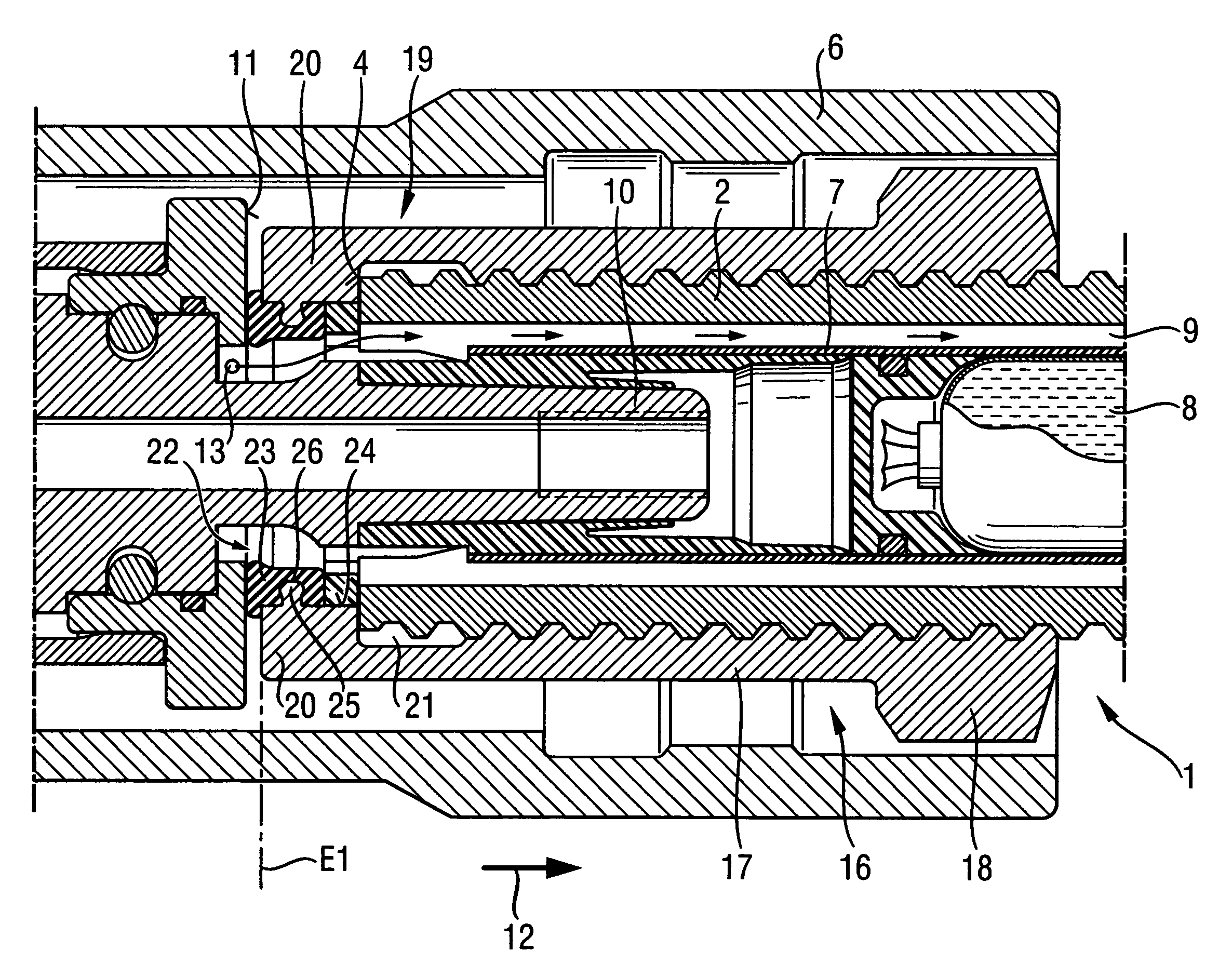
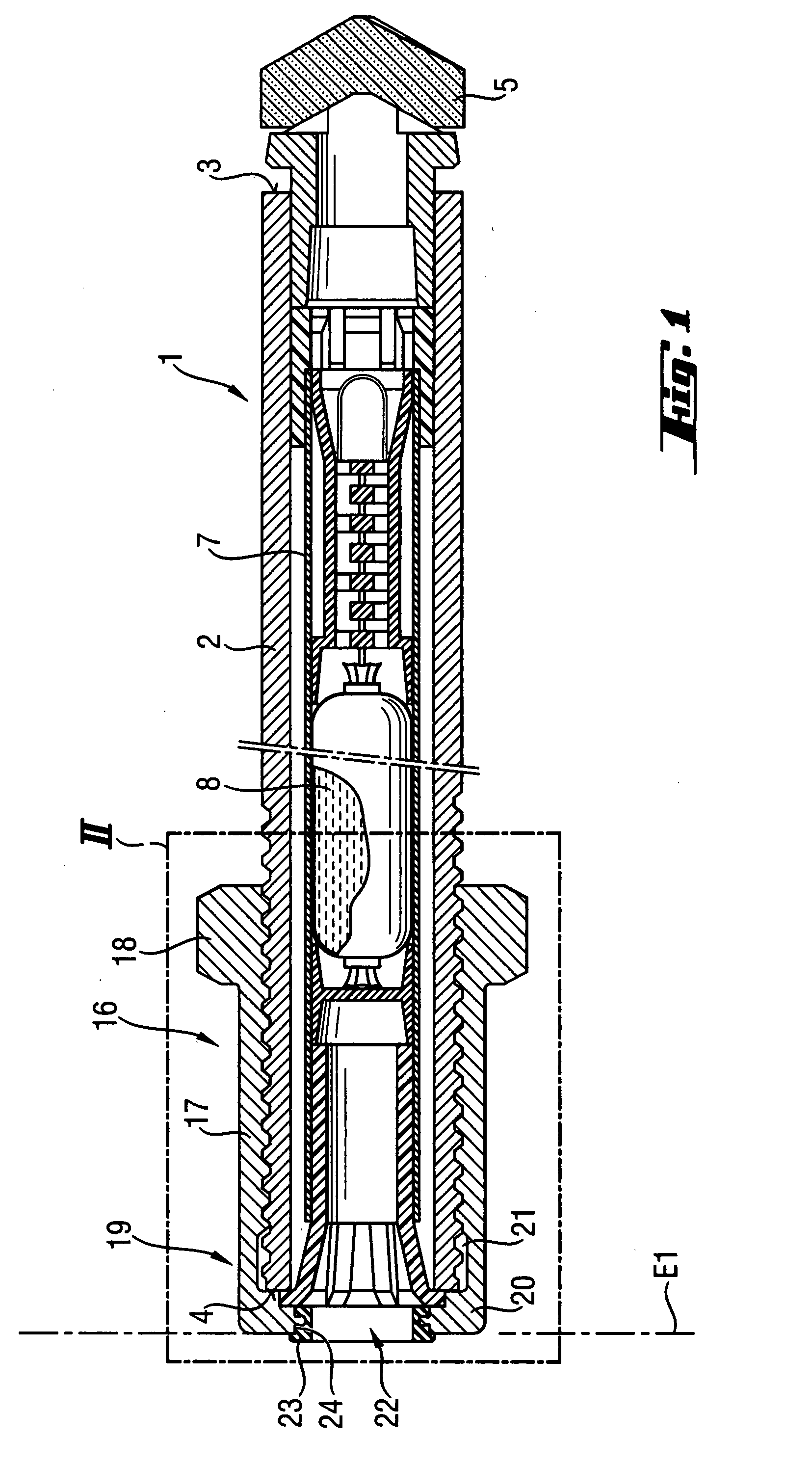
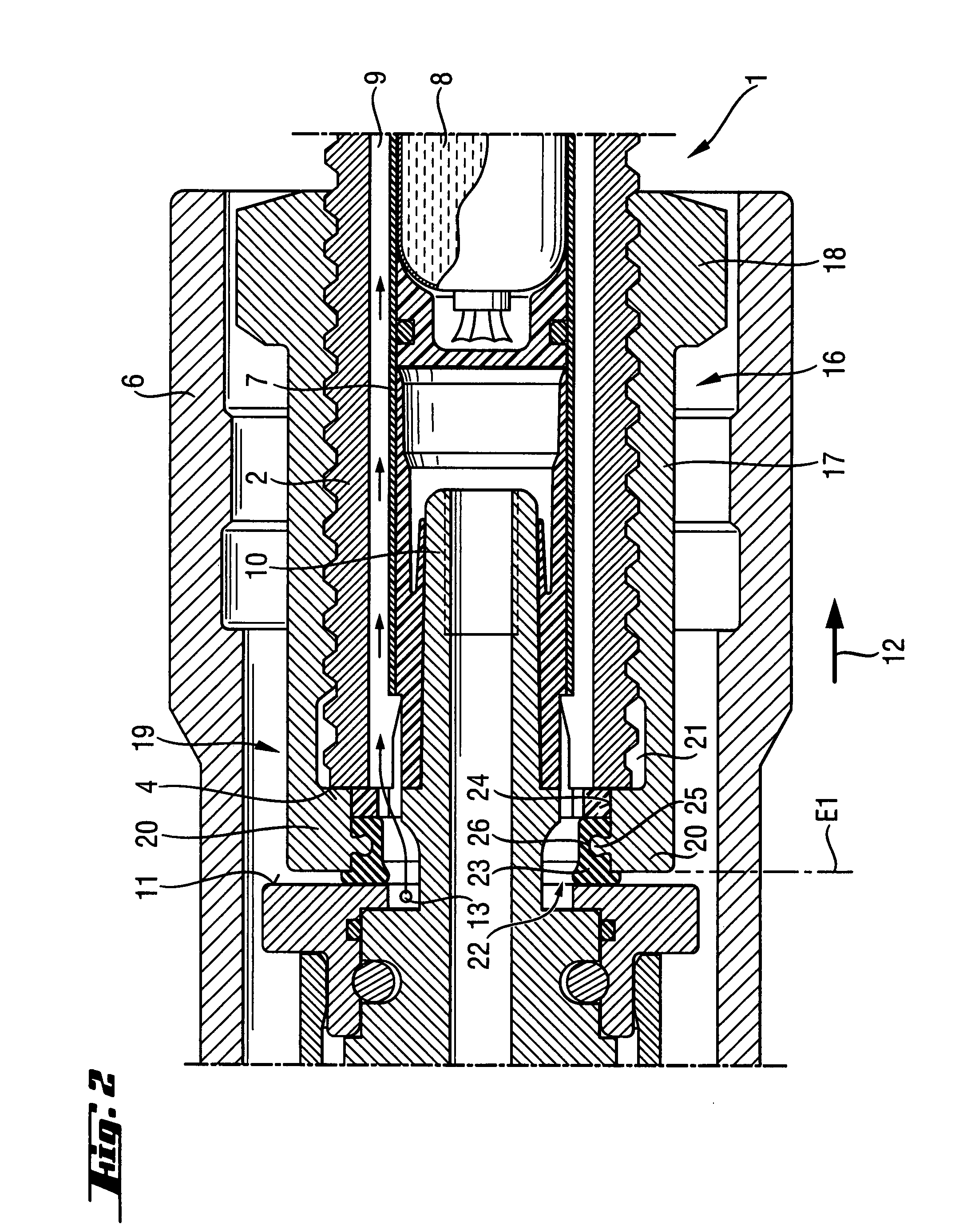
[0025] A self-drilling rock anchor 1, which is shown in FIGS. 1-2, is formed as a chemical connection anchor and includes an anchor tube 2 having a first end 3 at which a drilling head 5 is secured, and a second end 4. In the anchor tube 2, there is arranged an inner tube 7 for receiving a to-be-pressed out chemical mass 8. Between the outer wall of the inner tube 7 and the inner wall of the anchor tube 2, a rinsing water channel 9 is formed. During a drilling process, rinsing water is fed in the region of the drilling head 5 through the rinsing water channel 9 from the drilling tool or a feeding device. For connecting the self-drilling rock anchor 1 with a chuck 6 of the drilling tool, there is provided, on the second end 4 of the anchor tube 2, an adapter member 16 according to the present invention. In the embodiment shown in FIGS. 1-2, the adaptor member 16 is screwed on the anchor tube 2.

[0026] The adapter member 16 has a sleeve-shaped section 17 with a coupling section 18 for...


PUM


Abstract

An adapter member for connecting a self-drilling rock anchor (1; 31; 69) with a chuck (6) of a drilling tool, includes a sleeve-shaped section (17; 37) having a bottom (20; 40; 60; 80) provided at an end (19; 39) of the sleeve-shaped section (17; 37) for forming a receiving space (21) for connection with an end (4; 34) of the rock anchor (1; 31; 69), and a seal (23; 43; 63; 83) arranged in a region of the bottom (20; 40; 60; 80) and extending from the receiving space (21) to at least a plane (E1; E2; E3; E4) defined by the bottom.

Description

BACKGROUND OF THE INVENTION [0001] 1. Field of the Invention [0002] The present invention relates to an adapter member for connecting a self-drilling rock anchor with a chuck of a drilling tool and including a sleeve-shaped section having a coupling section for connection with the chuck, and a bottom provided at an end of the sleeve-shaped section for forming a receiving space for connection with an end of the rock anchor and having a through-opening through which a feeding nose is extendable. [0003] 2. Description of the Prior Art [0004] Self-drilling rock anchors, in particular chemical connection anchors and suitable drilling tools with rotatable chucks, and their use in mine and tunnel constructions are well known since long ago. The rock anchors serve primarily for stabilizing walls and hollow spaces in mines, tunnels, galleries, and the like. When hollow spaces are formed, mechanical properties and, in particular, the bearing capacity of strata are reduced. These strata are an...

Claims


Application Information

Patent Timeline
IPC IPC(8): E21D20/00
CPCE21B17/0426E21D20/026Y10T279/3493Y10T279/3418E21D2021/0053E21D21/0053E21D21/0033
Inventor KOEHLER, OLIVERLUDWIG, WOLFGANGHEEMANN, KAY
Owner HILTI AG
Why Eureka
Try Eureka