Transport fixing jig

a technology for fixing jigs and jigs, which is applied in the field of transport fixing jigs, can solve the problems of low heat resistance, affecting the processing efficiency of objects, and affecting the quality of objects, so as to achieve excellent heat resistance, high gripping force, and hardly contaminating the effect of processing objects

Active Publication Date: 2022-08-23
NITTO DENKO CORP
View PDF33 Cites 0 Cited by
  • Summary
  • Abstract
  • Description
  • Claims
  • Application Information

AI Technical Summary

Benefits of technology

[0019]According to the present invention, the transport fixing jig that has a high gripping force, hardly contaminates an object to be processed (object to be transported), and is excellent in heat resistance can be provided. In more detail, the transport fixing jig of the present invention includes the carbon nanotube aggregate arranged on the first base material, and hence can fix the object to be processed with the carbon nanotube aggregate. Accordingly, the transport fixing jig has a high gripping force, hardly contaminates the object to be processed (object to be transported), and is excellent in heat resistance. Further, when the first base material and the carbon nanotube aggregate are bonded to each other via the adhesive layer, and the ratio (adhesive layer / base material) between the linear expansion coefficient of the first base material and the linear expansion coefficient of the adhesive layer is set within a specific range, even under high temperature, the carbon nanotube aggregate hardly desorbs, and hence the object to be processed (object to be transported) can be satisfactorily fixed.

Problems solved by technology

However, in a related-art transport fixing jig, there is a problem in that the object to be processed is held by an elastic material, such as a resin, and hence the elastic material is liable to adhere to and remain on the object to be processed.
In addition, there is a problem in that the elastic material, such as a resin, has low heat resistance, and hence the gripping force of the jig is reduced under a high-temperature environment.
However, a transport fixing jig formed of such material involves a problem of inherently having a weak gripping force, and thus being unable to sufficiently hold the object to be processed even at normal temperature.
However, the method involving adsorbing the object to be processed under reduced pressure is effective only under an air atmosphere, and cannot be adopted under a vacuum in, for example, a CVD step.
In addition, the method involving fixing the object to be processed by the shape of the transport fixing jig involves, for example, the following problems.
The object to be processed is damaged, or a particle is produced, by contact between the object to be processed and the transport fixing jig.

Method used


Image

  • Transport fixing jig
  • Transport fixing jig

Examples


example 1

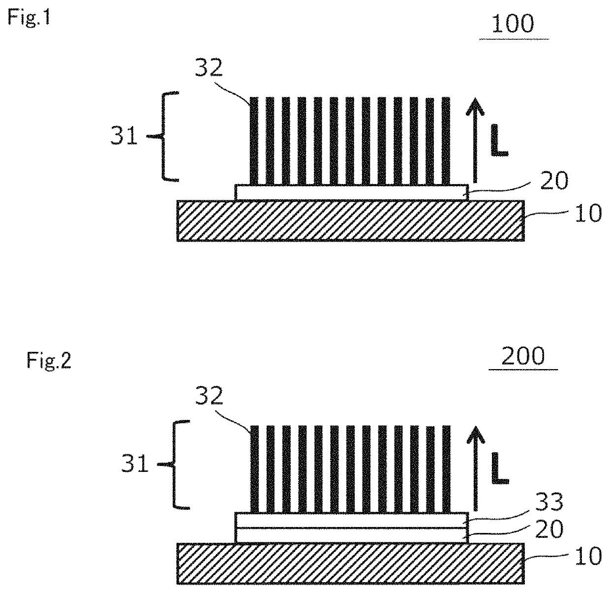
[0106]An adhesive (manufactured by ThreeBond Co., Ltd., product name: “TB3732,” binder: metal alkoxide, filler: alumina) was applied onto a first base material (made of ceramics; linear expansion coefficient: 8 ppm / ° C.) with a squeegee.

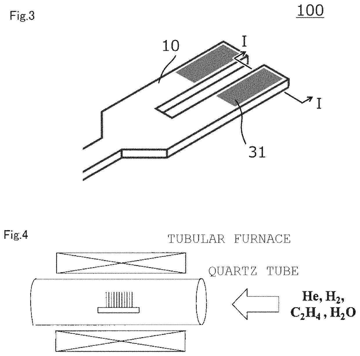
[0107]The carbon nanotube aggregate obtained in Production Example 1 was collected from the flat plate, and was arranged on the applied layer of the adhesive. At this time, the arrangement was performed so that the side of the carbon nanotube aggregate that had been in contact with the flat plate was brought into contact with the applied layer of the adhesive.

[0108]After that, a weight was placed on the side of the carbon nanotube aggregate opposite to the applied layer of the adhesive via a clean wafer, and a load of 50 g / cm2 was applied for 1 minute to bring the carbon nanotube aggregate and the applied layer of the adhesive into close contact with each other.

[0109]Next, a laminate obtained as described above was placed under normal temperature for...

example 2

[0111]A laminate was obtained in the same manner as in Example 1 except that an adhesive (manufactured by EM Japan Co., Ltd., product name: “G7716,” binder: silicate, filler: carbon) was used instead of the adhesive (manufactured by ThreeBond Co., Ltd., product name: “TB3732,” binder: metal alkoxide, filler: alumina). The laminate was placed under normal temperature for 2 hours and under an environment at 100° C. for 2 hours to cure the adhesive. Thus, a transport fixing jig including the first base material, the adhesive layer (thickness: 10 μm), and the carbon nanotube aggregate was obtained.

example 3

[0112]A laminate was obtained in the same manner as in Example 1 except that an adhesive (manufactured by AIN Co., Ltd., product name: “RG-57-2-3;” binder: organopolysiloxane, fillers: silicon dioxide (silica), titanium dioxide (titania), and potassium titanate, solvent: ethylene glycol dibutyl ether) was used instead of the adhesive (manufactured by ThreeBond Co., Ltd., product name: “TB3732,” binder: metal alkoxide, filler: alumina). The laminate was placed under an environment at 80° C. for 30 minutes, under an environment at 150° C. for 30 minutes, and under an environment at 400° C. for 2 hours to cure and calcine the adhesive. Thus, a transport fixing jig including the first base material, the adhesive layer (thickness: 20 μm), and the carbon nanotube aggregate was obtained.


PUM

PropertyMeasurementUnit
angleaaaaaaaaaa
angleaaaaaaaaaa
angleaaaaaaaaaa

Abstract

Provided is a transport fixing jig that has a high gripping force, hardly contaminates an object to be processed (object to be transported), and is excellent in heat resistance. The transport fixing jig of the present invention includes: a first base material; a carbon nanotube aggregate; and an adhesive layer arranged between the first base material and the carbon nanotube aggregate, wherein the first base material and the carbon nanotube aggregate are bonded to each other via the adhesive layer, and wherein a ratio (adhesive layer / base material) between a linear expansion coefficient of the first base material and a linear expansion coefficient of the adhesive layer is from 0.7 to 1.8.

Description

CROSS REFERENCE TO RELATED APPLICATIONS[0001]This application is a National Stage of International Application No. PCT / JP2017 / 010140 filed Mar. 14, 2017, claiming priority based on Japanese Patent Application No. 2016-055245 filed Mar. 18, 2016 and Japanese Patent Application No. 2017-046313 filed Mar. 10, 2017.TECHNICAL FIELD[0002]The present invention relates to a transport fixing jig.BACKGROUND ART[0003]In transporting a material, a production intermediate, a product, or the like (hereinafter sometimes referred to as “object to be processed”) in a manufacturing process for a semiconductor device or the like, the object to be processed is transported through use of a carrying member, such as a movable arm or a movable table (see, for example, Patent Literatures 1 and 2). In such transport, there is a demand for a member on which the object to be processed is to be mounted (transport fixing jig) to have such a strong gripping force as to prevent the object to be processed from shif...

Claims


Application Information

Patent Timeline
Patent Type & Authority Patents(United States)
IPC IPC(8): B32B9/04B65G49/07H01L21/673H01L21/687B32B5/02B32B7/12H01L21/677H01L21/683
CPCB65G49/07B32B5/02B32B7/12H01L21/677H01L21/67316H01L21/6835H01L21/68707B32B2255/20B32B2262/106H01L21/67132H01L21/67742
Inventor MASUDA, SHOTAROICHIKAWA, TOMOAKIMAENO, YOHEIHATAKEYAMA, YOSHIHARU
Owner NITTO DENKO CORP
Why Eureka
Try Eureka