Polymer jacket tube and cable terminal connector employing the same

a technology of polymer jacket and cable terminal, which is applied in the direction of cable junction, cable fitting, electric cable installation, etc., can solve the problems of deteriorating the performance of insulating oil or insulating gas, affecting the service life of the cable terminal, so as to improve the withstand voltage of pollution, the effect of reducing the number of steps and reducing the number of components

Inactive Publication Date: 2005-01-27
SHOWA ELECTRIC WIRE & CABLE CO
View PDF2 Cites 8 Cited by
  • Summary
  • Abstract
  • Description
  • Claims
  • Application Information

AI Technical Summary

Benefits of technology

[0026] Thirdly, in a case where the polymer covering is formed of a silicone polymer, the characteristic of pollution withstand voltage can be enhanced owing to the water repellency of the silicone polymer.
[0027] Fourthly, since the reception port of the insulation sleeve is located at a position lower than the polymer covering, the polymer jacket tube can be made finer than the prior-art polymer jacket tube, and in consequence of the fine polymer jacket tube, the projected cross-sectional area of the polymer jacket tube becomes small, with the result that even a short polymer jacket t

Problems solved by technology

Secondly, there has been the drawback that, when the outside diameter of the porcelain jacket tube 21 enlarges, the projected cross-sectional area thereof becomes large, resulting in the degradation of the characteristic of the pollution withstand voltage of the porcelain jacket tube 21, so an elongated porcelain jacket tube must be used to meet a predetermined characteristic of pollution withstand voltage.
Fourthly, there has been the drawback that, since the components such as epoxy seat 24, upper covering 25 and clamp metal fitting 32 are required, a large

Method used


Image

  • Polymer jacket tube and cable terminal connector employing the same
  • Polymer jacket tube and cable terminal connector employing the same
  • Polymer jacket tube and cable terminal connector employing the same

Examples


Embodiment Construction

[0036] Now, preferred embodiments of a polymer jacket tube according to the present invention and a cable terminal connector employing the polymer jacket tube will be described with reference to the drawings.

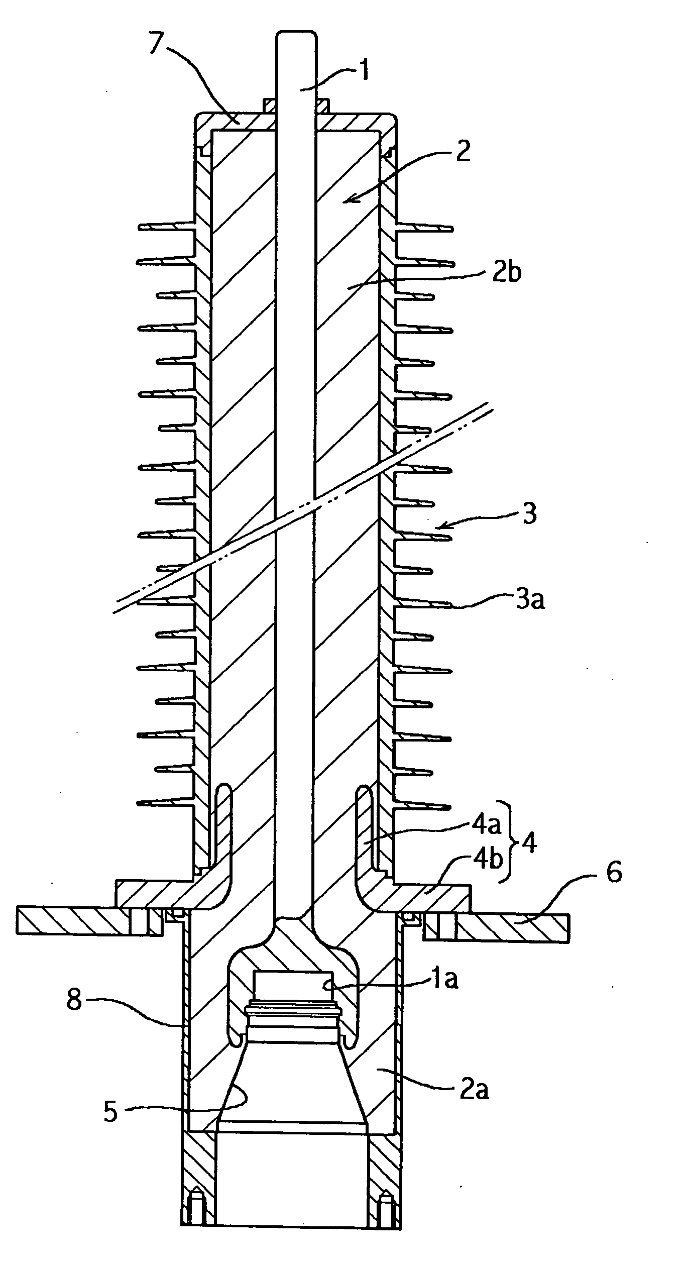
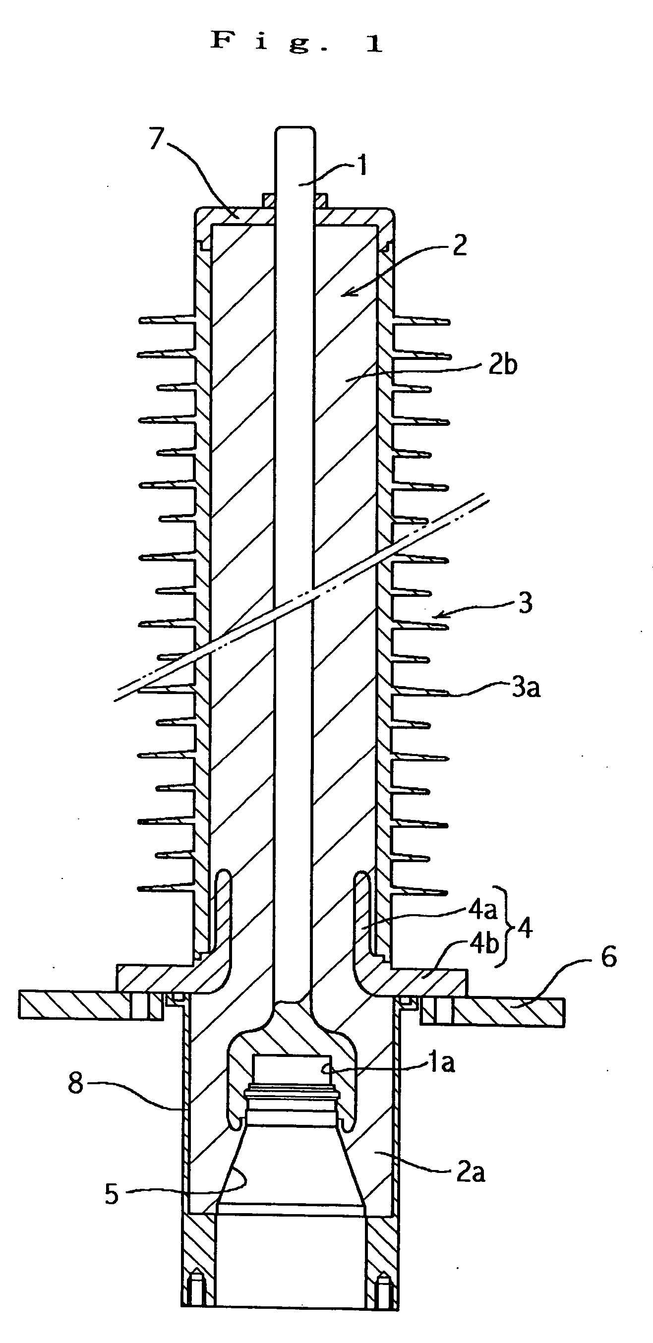
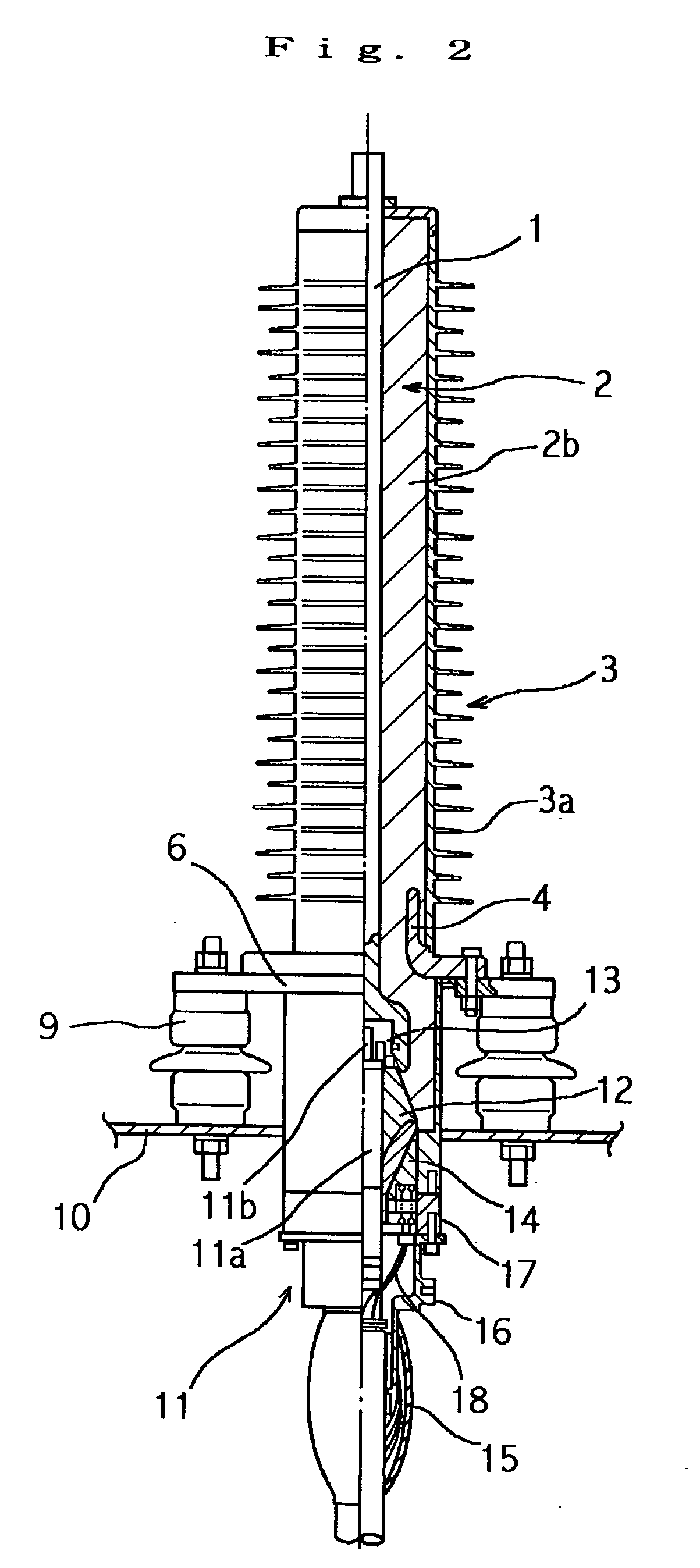
[0037]FIG. 1 shows a vertical sectional view of the polymer jacket tube of the present invention, while FIG. 2 shows a partly sectional view of an air termination for a cable which employs the polymer jacket tube of the present invention.

[0038] Referring to FIG. 1, the polymer jacket tube of the present invention includes a conductor bar 1 which has a conductor insertion hole 1a at its lower end part, a rigid insulation sleeve 2 which is disposed on the outer periphery of the conductor bar 1, and a polymer covering 3 which is disposed on the outer periphery of the insulation sleeve 2. Here, the insulation sleeve 2 is formed of a material of high mechanical strength, for example, a rigid plastic resin such as epoxy resin or FRP (fiber reinforced plastic). Besides, the polymer c...


PUM


Abstract

A polymer jacket tube includes a conductor bar 1 which has a conductor insertion hole 1a at its lower end part, a rigid insulation sleeve 2 which is provided at the outer periphery of the conductor bar 1, and a polymer covering 3 which is provided at the outer periphery of the insulation sleeve 2.
The insulation sleeve 2 includes a large-diameter insulation sleeve 2a which is provided at the outer peripheral part of the lower portion of the conductor bar 1, and a small-diameter insulation sleeve 2b which is provided at the outer peripheral part of the portion of the conductor bar 1 except the distal end part thereof, and an embedded metal fitting 4 for electrical stress relief is buried in the continuous portion of the large-diameter insulation sleeve 2a and the small-diameter insulation sleeve 2b.
Besides, a cone-shaped reception port 5 which receives the stress cone 12 of a cable terminal 11 is provided at the lower end part of the large-diameter insulation sleeve 2a, and this reception port 5 is held in communication with the conductor insertion hole 1a of the conductor bar 1.

Description

TECHNICAL FIELD [0001] This invention relates to a polymer jacket tube and a cable terminal connector employing the polymer jacket tube. More particularly, it relates to a polymer jacket tube which can attain the simplification of a structure, the lightening of a weight and the facilitation of on-site execution, and which need not be filled with an insulating compound such as insulating oil or insulating gas, and a cable terminal connector which employs the polymer jacket tube. BACKGROUND ART [0002] Heretofore, as a cable terminal connector of this type, one constructed as shown in FIG. 5 has been known. Referring to the figure, the cable terminal connector in the prior art includes a cable terminal 20, and a porcelain jacket tube 21 which envelops the cable terminal 20, and which is filled with an insulating compound 22 such as insulating oil or insulating gas. [0003] Here, an annular bottom metal fitting is mounted on the bottom part of the porcelain jacket tube 21, and an epoxy s...

Claims


Application Information

Patent Timeline
IPC IPC(8): H01B17/00H01B17/26H02G1/14H02G15/064H02G15/068
CPCH02G15/068H02G15/064H01B17/00H02G15/18
Inventor HIROSHI, SUGITANOBUYUKI, SEMA
Owner SHOWA ELECTRIC WIRE & CABLE CO
Why Eureka
Try Eureka