Sliding mechanism

a sliding mechanism and mechanism technology, applied in mechanical devices, instruments, gearing, etc., can solve problems such as degrading the sliding mechanism

Inactive Publication Date: 2010-03-11
SHENZHEN FUTAIHONG PRECISION IND CO LTD +1
View PDF5 Cites 5 Cited by
  • Summary
  • Abstract
  • Description
  • Claims
  • Application Information

AI Technical Summary

Problems solved by technology

However, after repeatedly usage, the torsion spring may wear out and thus fail to function properly, thereby degrading the sliding mechanism.

Method used


Image

  • Sliding mechanism
  • Sliding mechanism
  • Sliding mechanism

Examples


Embodiment Construction

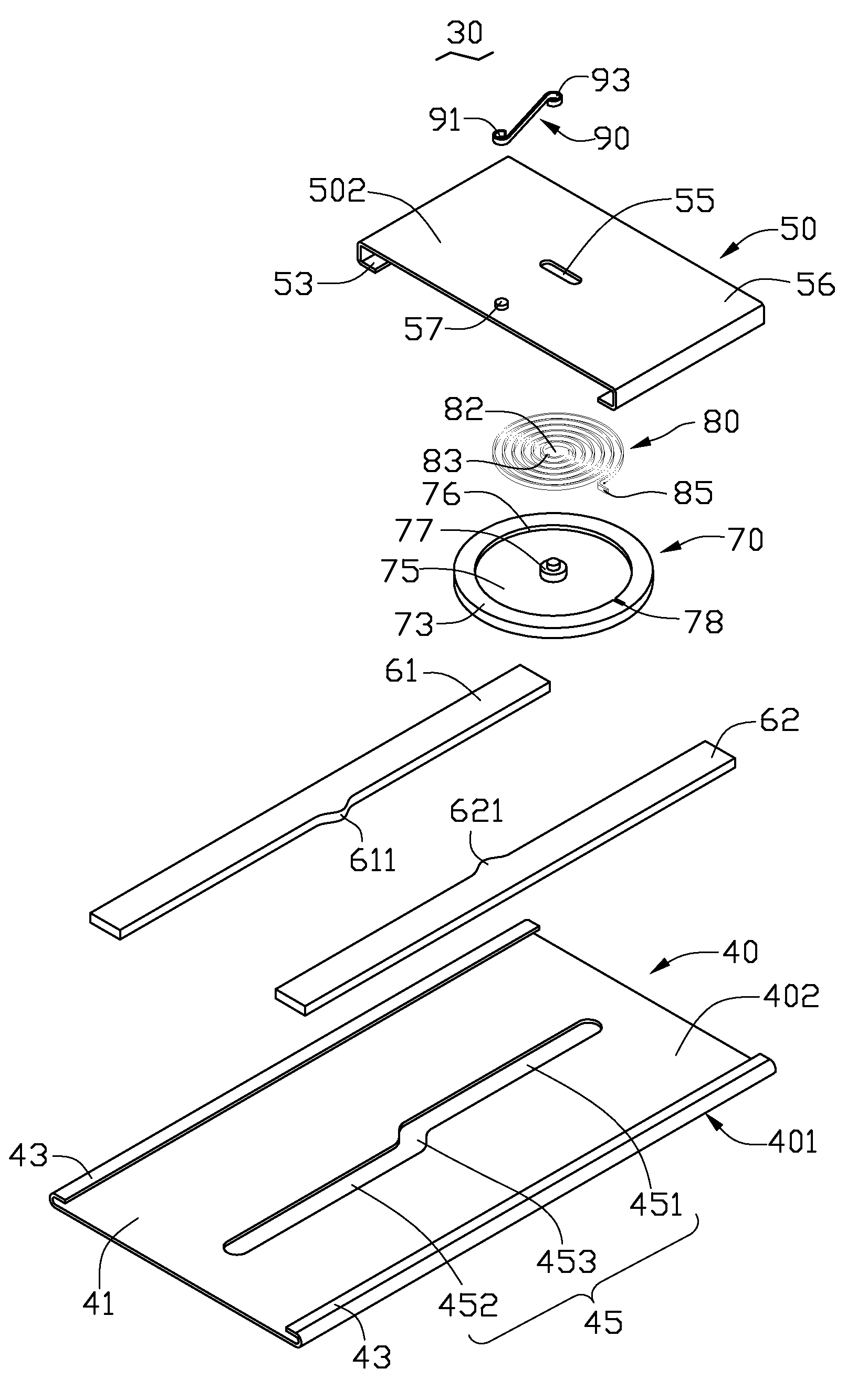
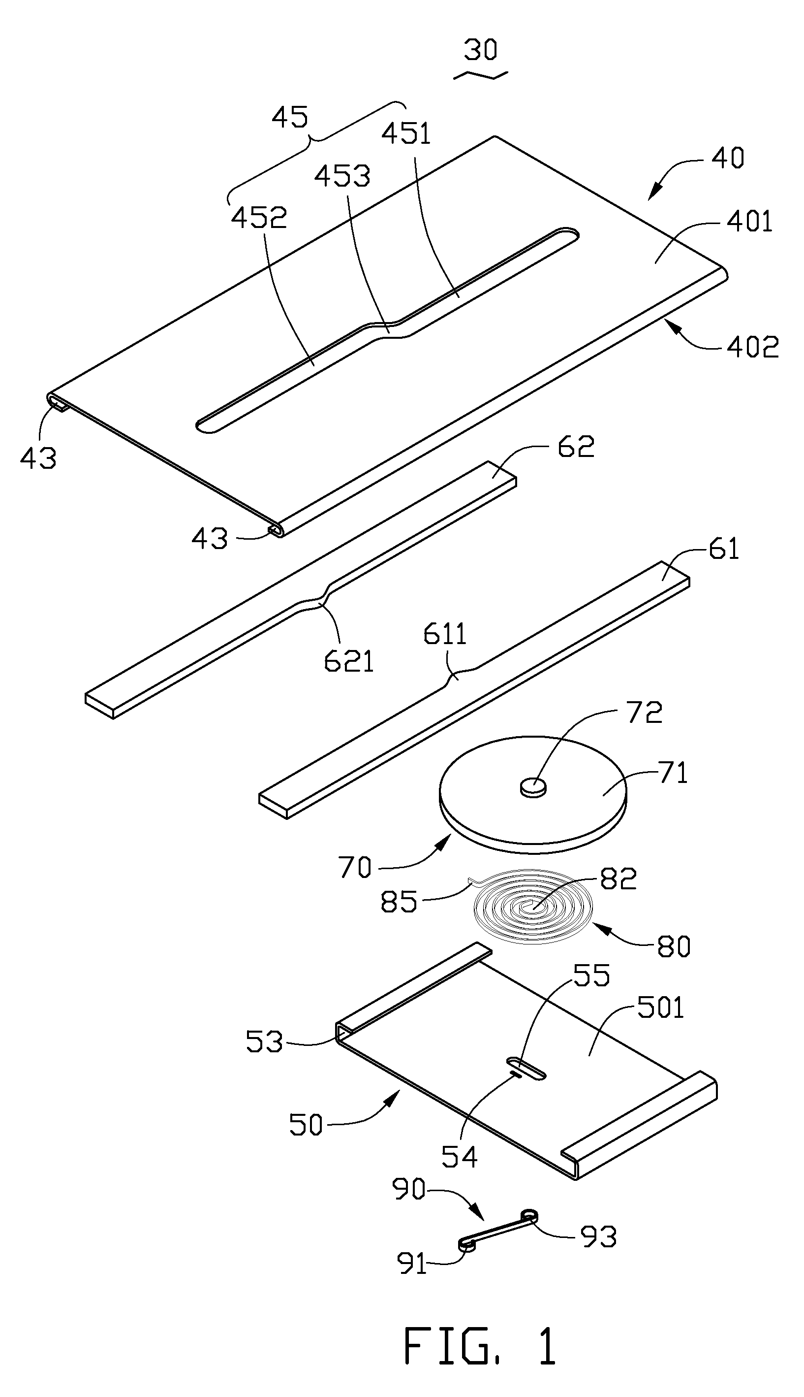
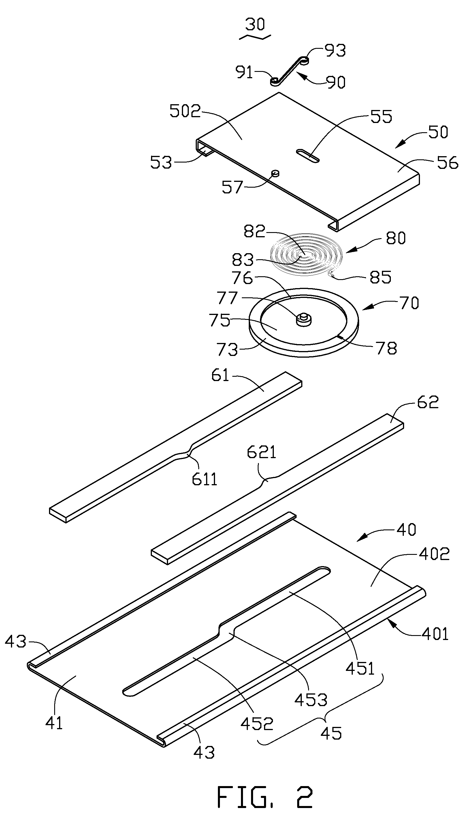
[0014]FIGS. 1 and 2 show an exemplary sliding mechanism 30 for portable electronic devices, such as mobile phone terminals, digital cameras and etc. The sliding mechanism 30 includes a body section 40, a cover section 50, first friction board 61, second friction board 62, a rolling disk 70, a coil spring 80 and an elastic member 90.

[0015]The body section 40 includes a top surface 401 and a bottom surface 402. The opposite edges of the body section 40 may be bent inwardly to form two rails 43. The body section 40 defines a sliding slot 45. The sliding slot 45 includes a first slot section 451, a second slot section 452 and a third slot section 453. The third slot section 453 communicates with the first sliding portion 451 and the second slot section 452. The first slot section 451 is substantially parallel with the second slot section 452, but the first slot section 451 is offset to (not coaxial with) the second slot section 452.

[0016]The cover section 50 includes a top surface 501 a...


PUM


Abstract

A sliding mechanism used in a portable electronic device is described. The sliding mechanism includes a body section, a cover section, a rolling disk and a coil spring. The rolling disk is fixed to the cover section. A center of the coil spring is fixed to a center of the rolling disk. An end of the coil spring is fixed to a periphery of the rolling disk. When the rolling disk rotates relative to the body section, the coil spring generates a force towards or against the sliding direction of the cover section.

Description

BACKGROUND[0001]1. Field of the Invention[0002]The present invention relates to sliding mechanisms and, particularly, to a sliding mechanism used in a portable electronic device.[0003]2. Description of Related Art[0004]Slide-type portable electronic device usually includes a main housing, a slidable housing and a sliding mechanism. The sliding mechanism drives the slidable housing to slide with respect to the main housing.[0005]The sliding mechanism usually includes a body section, a cover section and a torsion spring. One end of the torsion spring is fixed to the body section, and the other end of the torsion spring is fixed to the cover section. The cover section can slide relative to the body section by releasing the torsion force of the torsion spring. Due to the main housing and the slidable housing fixed to the body section and the cover section, the slidable housing can slide relative to the main housing.[0006]However, after repeatedly usage, the torsion spring may wear out a...

Claims


Application Information

Patent Timeline
Patent Type & Authority Applications(United States)
IPC IPC(8): F16C29/02
CPCY10T74/22H04M1/0237
Inventor ZHANG, YUHUANG, GUO-ZHAO
Owner SHENZHEN FUTAIHONG PRECISION IND CO LTD
Why Eureka
Try Eureka