
Quantitative analysis experiment device of influence rule on tooth surface friction force by torsional vibration of shaft system
A shafting torsional vibration, quantitative analysis technology, applied in the direction of measuring devices, vibration testing, machine/structural component testing, etc., can solve the problems that have not been found to study the torsional vibration of shafting
- Summary
- Abstract
- Description
- Claims
- Application Information
AI Technical Summary
Problems solved by technology
Method used
Image

Examples
Embodiment Construction
[0031] The present invention will be described in more detail below with examples in conjunction with the accompanying drawings.
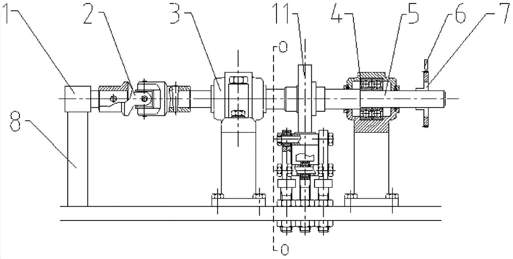
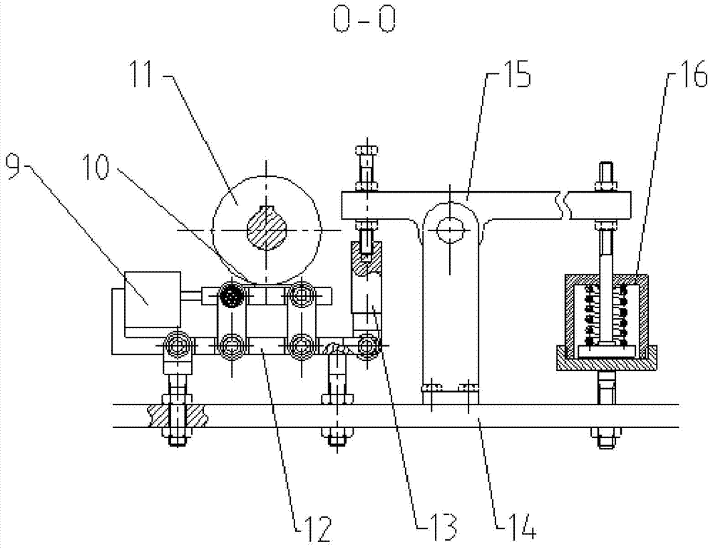
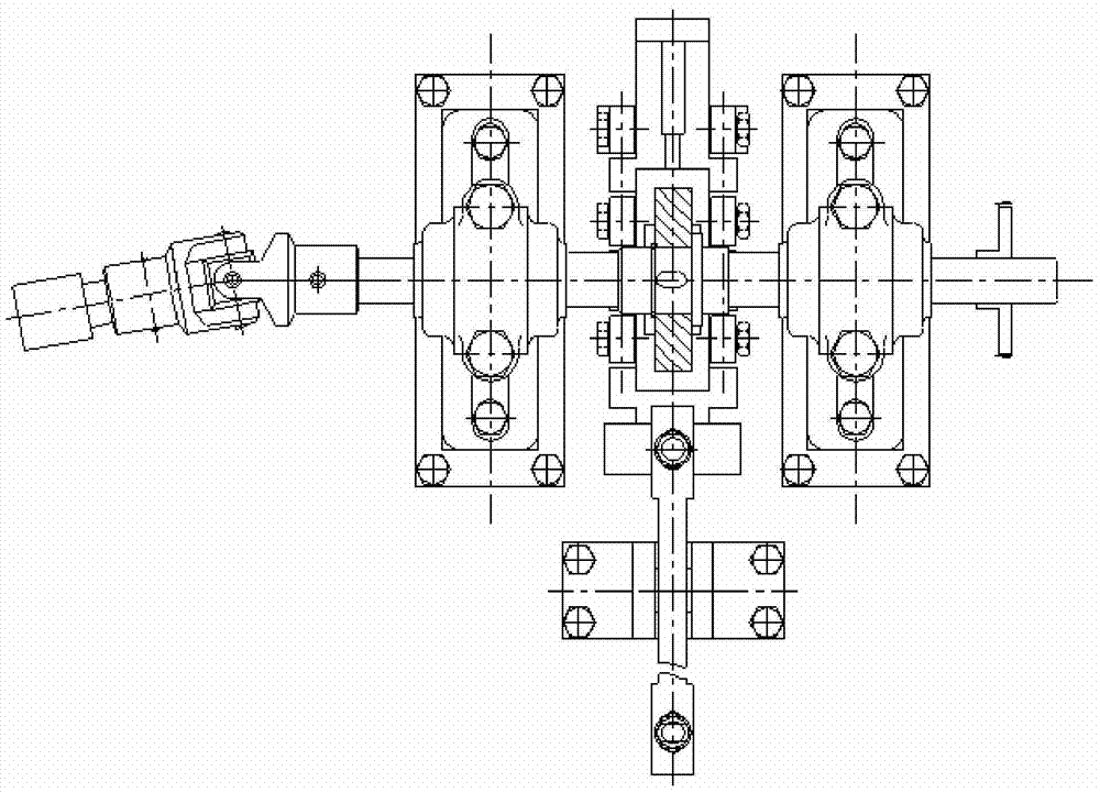
[0032] combine as figure 1 , figure 2 and image 3 , the quantitative analysis system includes motor 1, universal joint coupling assembly 2, front bearing assembly 3, rear bearing assembly 4, shaft 5, magnetoelectric sensor 6, gear plate 7, motor base 8, lateral force sensor 9, friction plate 10, rolling plate 11, friction lining support assembly 12, vertical force sensor 13, base 14, lever assembly 15 and load assembly 16. The motor 1 is fixed on the base 14 through the motor base 8 , and the output shaft of the motor 1 is connected with the shaft 5 through the universal joint assembly 2 . The shaft 5 is supported by deep groove ball bearings; the rolling disc 11 is fixed on the shaft 5 , and the rolling disc 11 is in contact with the friction plate 10 . The friction plate 10 is placed on the friction plate support assembly 12 , and the suppo...
PUM
 Abstract
Description
Claims
Application Information