High-frequency vibration motor for electric toothbrush

A technology of high-frequency vibration and electric toothbrush, applied in electric components, dentistry, electrical components, etc., can solve the problems of short service life, difficult positioning, complex structure, etc., and achieve the effect of long service life, easy manufacturing and simple processing technology

Active Publication Date: 2011-06-29
DONGGUAN LEBOND ELECTRONICS TECH CO LTD
View PDF5 Cites 49 Cited by
  • Summary
  • Abstract
  • Description
  • Claims
  • Application Information

AI Technical Summary

Problems solved by technology

[0003] The above three structures all have the disadvantages of complex structure, difficult positioning and short service life

Method used


Image

  • High-frequency vibration motor for electric toothbrush
  • High-frequency vibration motor for electric toothbrush
  • High-frequency vibration motor for electric toothbrush

Examples


Embodiment approach 1

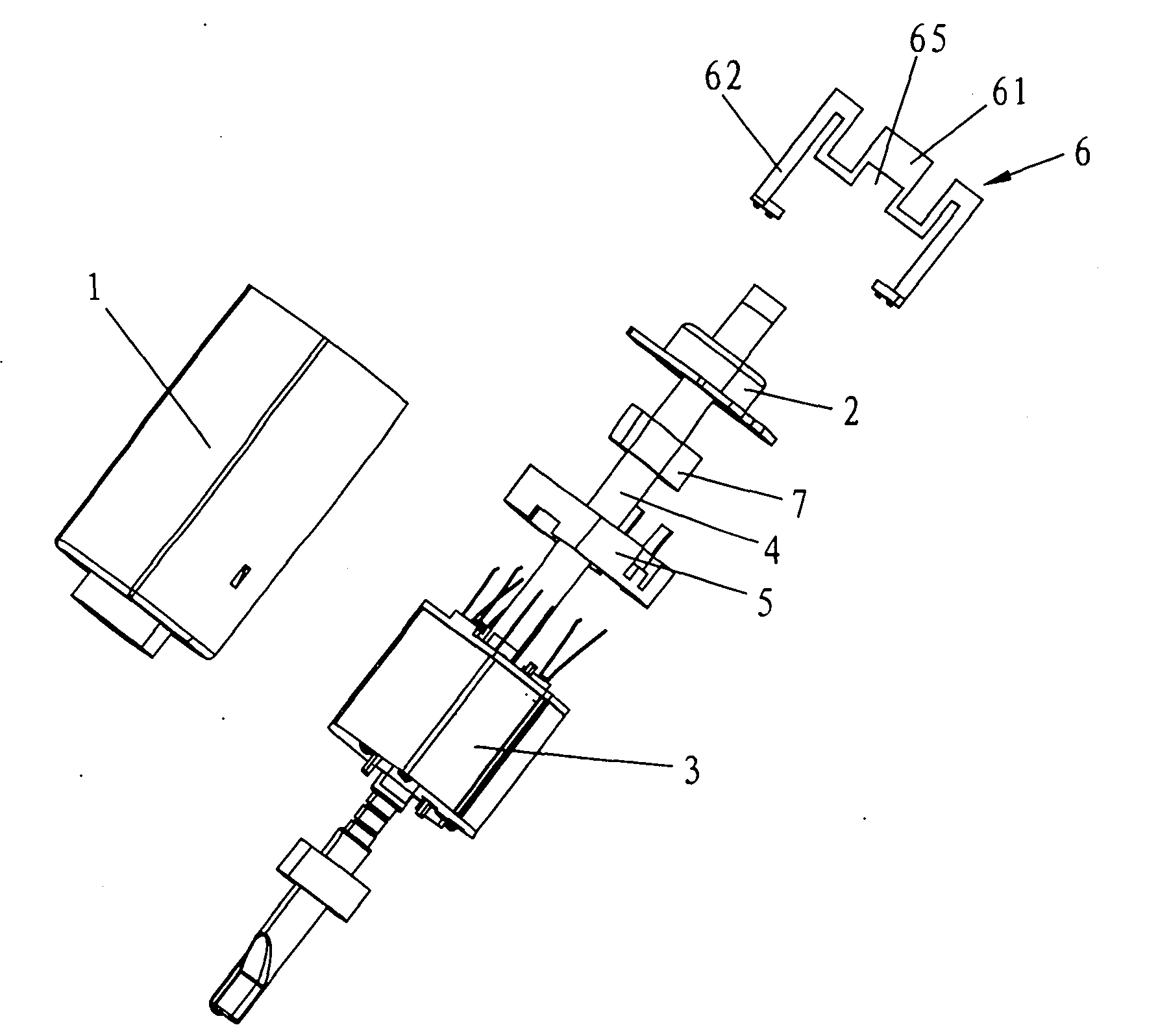
[0039] See figure 1 , 2 , 3, and 19, the present invention includes a casing 1 and a rear cover 2 with a cover on the casing 1, and the casing 1 is provided with a stator 3, a rotating shaft 4, an adjustment pad 5, a bearing 7, a stator 3, and 5 sets of adjustment pads Set on the rotating shaft 4, the output end of the rotating shaft 4 passes through the rear cover 2, and the output end of the rotating shaft 4 is connected with the rear cover 2 through the spring leaf 6.

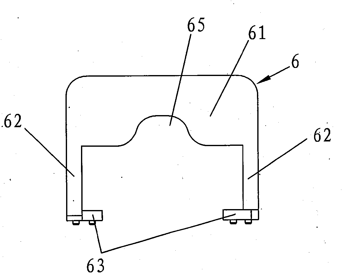
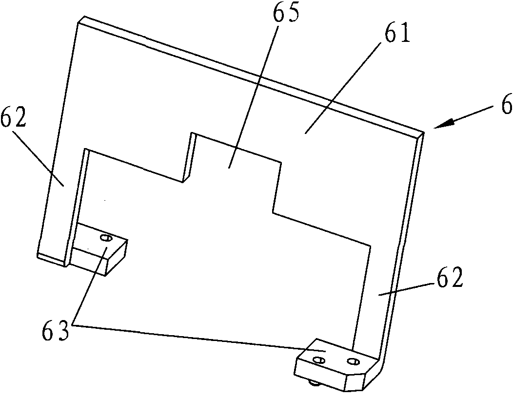
[0040] Between the left and right parts of the spring piece 6 is a rotationally symmetrical structure along the center of the spring piece main body 61. The spring piece 6 includes a spring piece main body 61, and the left and right sides of the spring piece main body 61 are respectively formed with elastic arms 62 that can be twisted and deformed as the rotating shaft 4 rotates. , the output end of the rotating shaft 4 is clamped at the center of the spring body 61, the top of the elastic arm 62 is connect...

Embodiment approach 2

[0044] See Figure 4 , 5 As shown, the difference between this embodiment and Embodiment 1 is that the top of the elastic arm 62 is connected to the spring body 61 by a connecting arm 64. The connecting arm 64 is arranged vertically, and its top is connected to the top of the elastic arm 62. Its bottom is connected to the bottom of the main body 61 of the elastic piece, and the addition of the connecting arm 64 can increase the elastic deformation range of the spring piece 6 . Of course, the top of the elastic arm 62 may also be connected to the spring body 61 through a plurality of end-to-end connection arms 64 , and other structures and principles are the same as those in the first embodiment.

Embodiment approach 3

[0046] See Figure 6-8As shown, the difference between this embodiment and Embodiment 1 is that the elastic body 61 of the spring 6 is a sheet structure located on a plane perpendicular to the elastic arm 62 , and the elastic body 61 is perpendicular to the elastic arm 62 . The output end of the rotating shaft 4 is formed with a flat post 41, and the center of the shrapnel main body 61 is provided with a bayonet 66 that matches the post 41. The bayonet 66 can be a flat hole, a Z-shaped hole or a hole of other shapes. , the clamping column 41 is clamped in the bayonet socket 66, and other structures and principles are the same as those in Embodiment 1.


PUM


Abstract

The invention relates to the technical field of electric toothbrushes, in particular to a high-frequency vibration motor for an electric toothbrush. The high-frequency vibration motor for the electric toothbrush comprises a shell and a rear cover, wherein a stator, a rotating shaft and an adjusting pad are arranged in the shell; the output end of the rotating shaft is connected with the rear cover through a spring piece; the spring piece comprises a spring piece main body and an elastic arm; the motor generates power to drive the rotating shaft to rotate reciprocally so as to drive the springpiece connected with the rotating shaft to twist to generate torsional deformation; when the frequency of the motor generating reciprocating movement is close to or reaches the torsional resonant frequency of the spring piece, the torsional vibration amplitude of the spring piece reaches the maximum so that the swinging amplitude of the motor reaches the maximum; because of the influence of the reluctance force of the motor per se, the vibration amplitude of an overall system reaches a balanced state, and the spring piece and the motor generate movement under the balanced condition. The high-frequency vibration motor for the electric toothbrush is easy to manufacture and position, along with reasonable structure, less elements, simple machining process, low cost and long service life.

Description

Technical field: [0001] The invention relates to the technical field of electric toothbrushes, in particular to a high-frequency vibration motor of an electric toothbrush. Background technique: [0002] In the prior art, the high-frequency vibration motors used in electric toothbrushes have a variety of internal structures, and their vibration generating units are even more diverse. For example, the Chinese patent with the patent publication number CN101554342A shows an electric toothbrush driving device, Among them, there are three structural forms of the vibration unit: first, the damping device includes a fixed head fixedly sleeved in the inner cavity of the housing, and one end of the fixed head protrudes from the outer contour of the end surface opposite to the two ends. A clamping column, the middle part of which is provided with a through hole, and one end of the rotating shaft passing through the through hole is fixedly connected with a follower, and the follower pro...

Claims


Application Information

Patent Timeline
Patent Type & Authority Applications(China)
IPC IPC(8): H02K7/065
CPCH02K33/00A61C17/16
Inventor 王凤梅
Owner DONGGUAN LEBOND ELECTRONICS TECH CO LTD
Why Eureka
Try Eureka