
Floating cushion sub

a cushion and sub-frame technology, applied in the field of cushions, can solve problems such as unsatisfactory results, and achieve the effect of effective handling

Inactive Publication Date: 2001-12-25
FOREMOST INDS
View PDF10 Cites 46 Cited by
  • Summary
  • Abstract
  • Description
  • Claims
  • Application Information

AI Technical Summary

Benefits of technology

Accordingly, it is an object of the present invention to provide a cushion sub having both axial and torsional vibration absorbing characteristics capable of effectively handling the types of forces being experienced in modern drilling techniques.
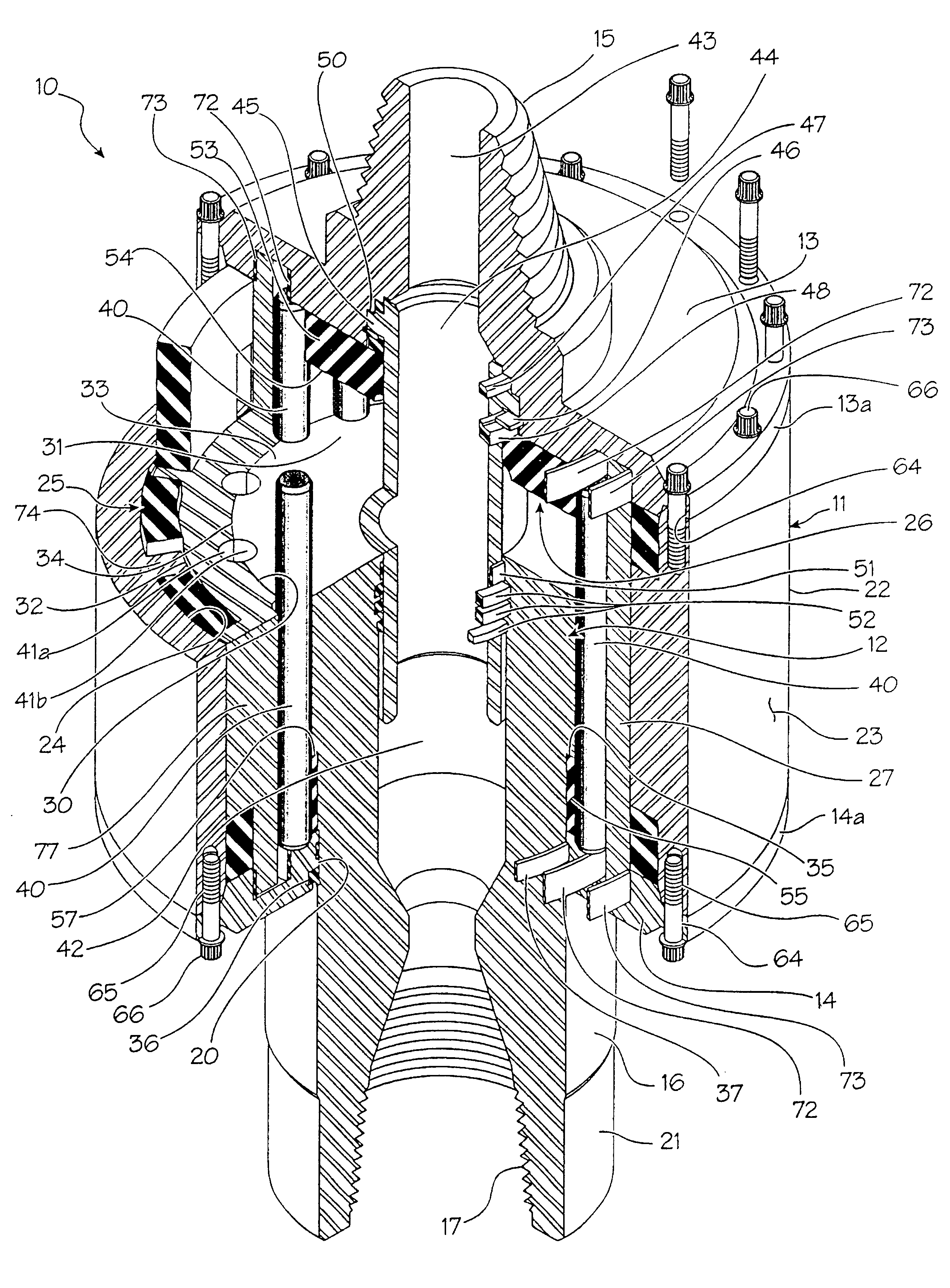
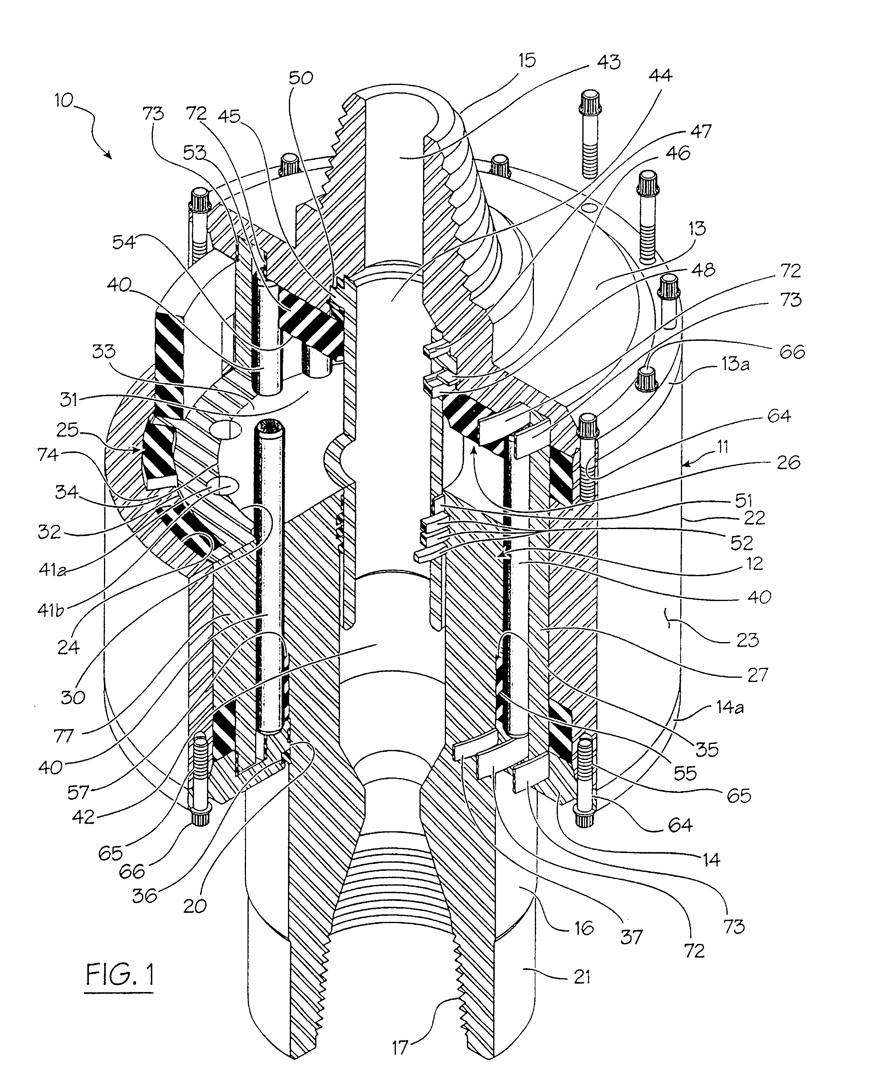
The cushion sub of the present invention, which is used for connection between a driving member and a driven member in a drill string to effectively absorb both torsional and axial vibrations in the drill string, is of the type including a main body having an outer casing member. The casing member includes a first end cap which is provided with a first connection means at one end of the main body for rigid connection to one of the driving and driven members of the drill string, usually the driving member. A cylinder member is disposed within the outer casing member and defines an inner cylinder chamber, and a piston member is disposed within the cylinder chamber for axial movement between extreme inward and outward positions. A piston shaft extends from the piston member through the other end of the casing member. The piston shaft has second connection means at a free end thereof for rigid connection to the other of the driving and driven members of the drill string, usually the driven member. The cylinder member has internal spline means cooperating with external spline means on the piston member for preventing relative rotation between the piston member and the cylinder member while permitting the axial movement of the piston member relative to the cylinder member between the inward and outward positions. Cushion means is provided at opposite ends of the cylinder chamber for engagement by the piston in either of the extreme positions for absorbing axial vibrating and preventing transmission thereof between the piston member and the cylinder member.
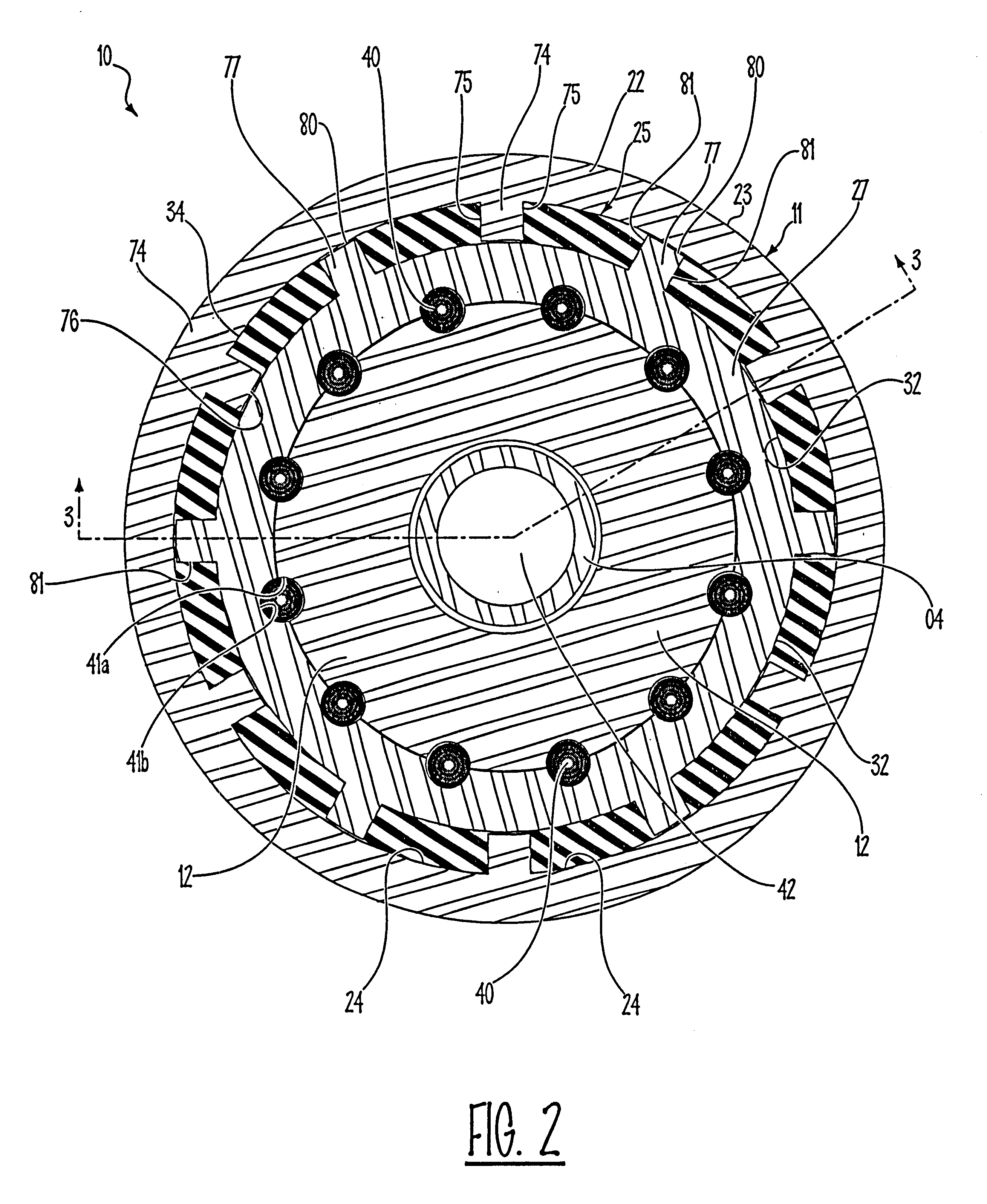
According to one aspect of the present invention, the cylindrical member has an outer surface disposed radially inward from an inner surface of the casing member so as to form an annular space therebetween. First circumferentially spaced vane members project radially outward from and are integrally formed with the outer surface of the cylinder member, the vane members extending axially along the outer surface within the annular space. Second radially inward projecting vane members are integrally formed with the inner surface of the casing member, the second vane members being circumferentially spaced from each other and being disposed between and circumferentially spaced form the first vane members. Resilient cushion means is disposed in the annular space between and separates the first and second vane members, so as to absorb torsional vibrations and thereby prevent transmission of torsional vibrations between the cylinder member and the casing member.
According to another aspect of the present invention, the casing member has a cylindrical inner surface defining a closed chamber, and a plurality of first, circumferentially spaced, vane members project radially inward from the inner surface of the casing member. A plurality of second, circumferentially spaced vane members are affixed to the cylinder member and project radially outward between, but circumferentially spaced between the first vane members in the closed chamber. A resilient cushion medium occupies the closed chamber and separates the first and second vane members. The cushion medium formed in situ in said closed chamber by injecting said medium in a fluid state into said closed chamber is thereby bonded to said first and second vane members so that the cushion medium effectively absorbs torsional vibrations being transmitted between the cylinder member and the outer casing.

Problems solved by technology

This has not proven completely satisfactory, however, in that the resilient means used in the connector of this patent has not been designed for the transmission of the axial forces present in the downhole hammer type drilling.

Method used


Image

  • Floating cushion sub
  • Floating cushion sub
  • Floating cushion sub

Examples


Embodiment Construction

1. Technical Field

This invention relates to a cushion sub of a type for absorbing vibrations being transmitted to a drill head by a drill pipe during the drilling of a bore hole.

2. Background Art

It is well known to include a cushion sub below the drill head of a drilling rig and through which the turning force of the drill head is transmitted to the uppermost drill pipe section to thereby rotate the drill string within the bore being drilled. Such cushion subs have taken a number of different forms, the design of which takes into account different features of the drilling operation in association with which the cushion sub will be used. For example, it is common in a drilling operation to force the drilling bit into engagement with the bottom of the bore and to achieve the cutting action due to rotation motion only of the bit. A cushion sub designed for this type of drilling must be capable of absorbing a significant portion of both the torsional and axially vibrations developed by ...


PUM


Abstract

A cushion sub for absorbing both axial and torsional vibration in a drill string and including an outer casing connectable at one end to a section of a drill string, and an inner piston reciprocally mounted in a cylinder within the casing, the piston having a shaft projecting from the other end of the casing connectable to another section of the drill string. The cylinder includes a first cushion device at opposite ends thereof for engagement by the piston to absorb axial vibrations. A spline type connection prevents relative rotation between the piston and the cylinder. The cylinder is mounted for arcuate turning in a chamber within the casing, but the cylinder has vanes which are interposed between vanes fixed to the casing, and elastomeric material between the vanes of the cylinder and the vanes of the casing absorbs torsional vibrations being transmitted between the cylinder and the casing. The elastomeric material is preferably formed in situ as an integral mass in the chamber of the casing by pouring the elastomeric material in a fluid state into the chamber.

Description

DESCRIPTION OF THE INVENTION1. Technical FieldThis invention relates to a cushion sub of a type for absorbing vibrations being transmitted to a drill head by a drill pipe during the drilling of a bore hole.2. Background ArtIt is well known to include a cushion sub below the drill head of a drilling rig and through which the turning force of the drill head is transmitted to the uppermost drill pipe section to thereby rotate the drill string within the bore being drilled. Such cushion subs have taken a number of different forms, the design of which takes into account different features of the drilling operation in association with which the cushion sub will be used. For example, it is common in a drilling operation to force the drilling bit into engagement with the bottom of the bore and to achieve the cutting action due to rotation motion only of the bit. A cushion sub designed for this type of drilling must be capable of absorbing a significant portion of both the torsional and axia...

Claims


Application Information

Patent Timeline
Patent Type & Authority Patents(United States)
IPC IPC(8): E21B17/07E21B17/02
CPCE21B17/07E21B17/073
Inventor SECORD, DOUGLAS C.
Owner FOREMOST INDS
Learn More