
Ground pay-off rack

A technology of pay-off frame and fixed plate, which is applied in the field of ground wire, spread wire, and cable support, and can solve the problems that cannot be realized well.

Inactive Publication Date: 2012-07-04
枣庄矿业(集团)有限责任公司供电工程处
View PDF7 Cites 6 Cited by
  • Summary
  • Abstract
  • Description
  • Claims
  • Application Information

AI Technical Summary

Problems solved by technology

There are a lot of inconveniences in the existing tools, and the purpose cannot be well achieved

Method used


Image

  • Ground pay-off rack
  • Ground pay-off rack
  • Ground pay-off rack

Examples


Embodiment Construction

[0020] The present invention will be further described below in conjunction with accompanying drawing and specific embodiment:

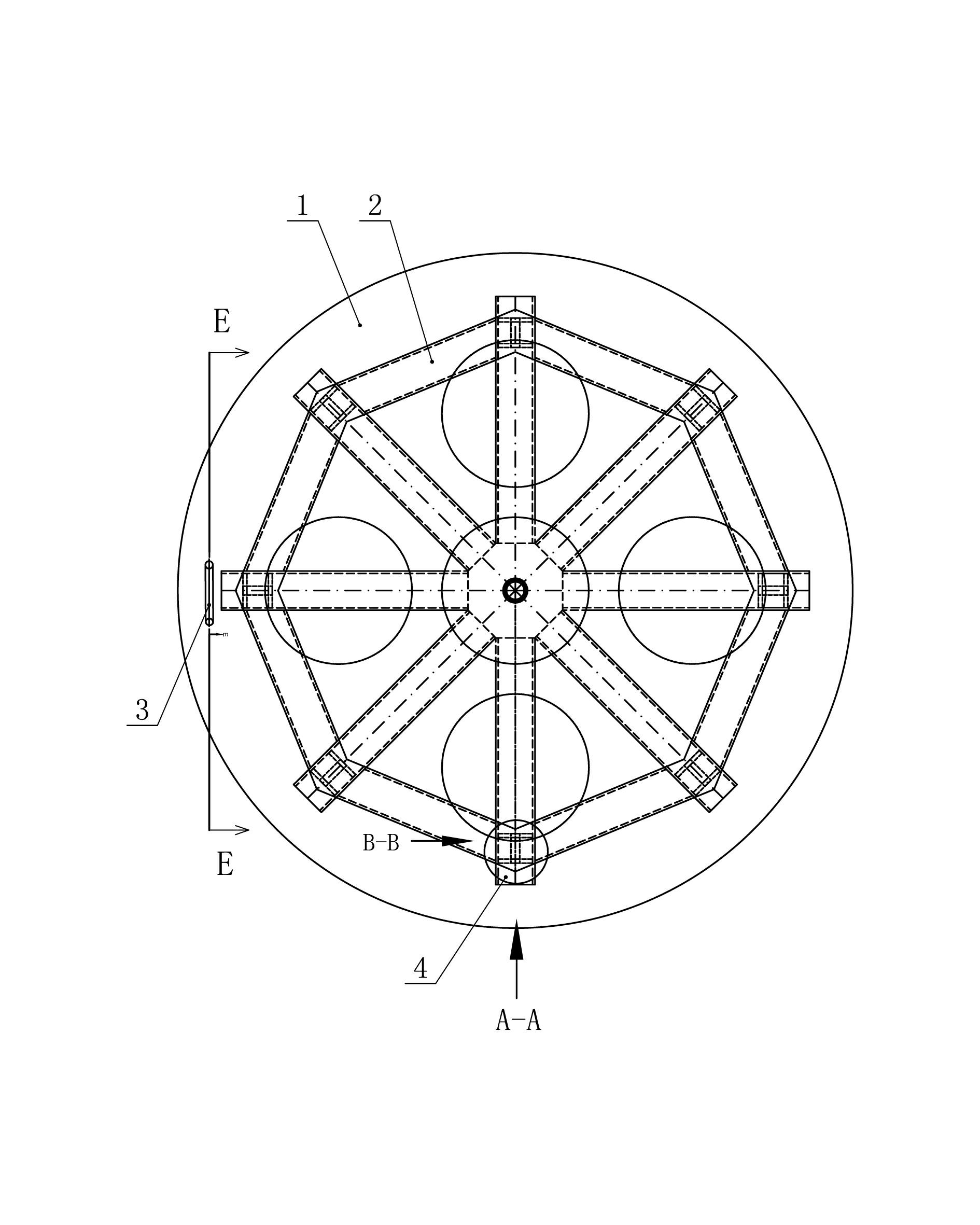
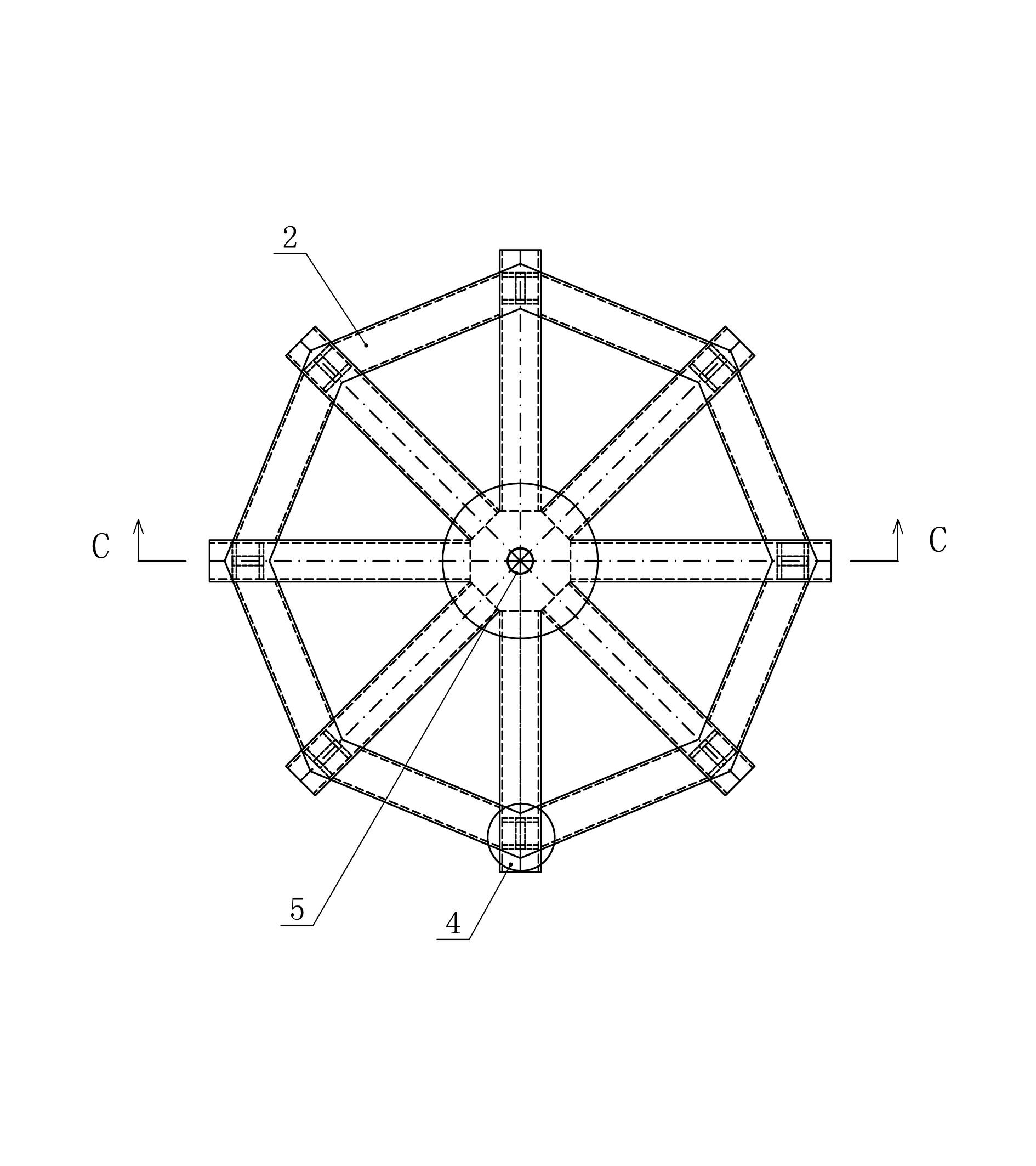
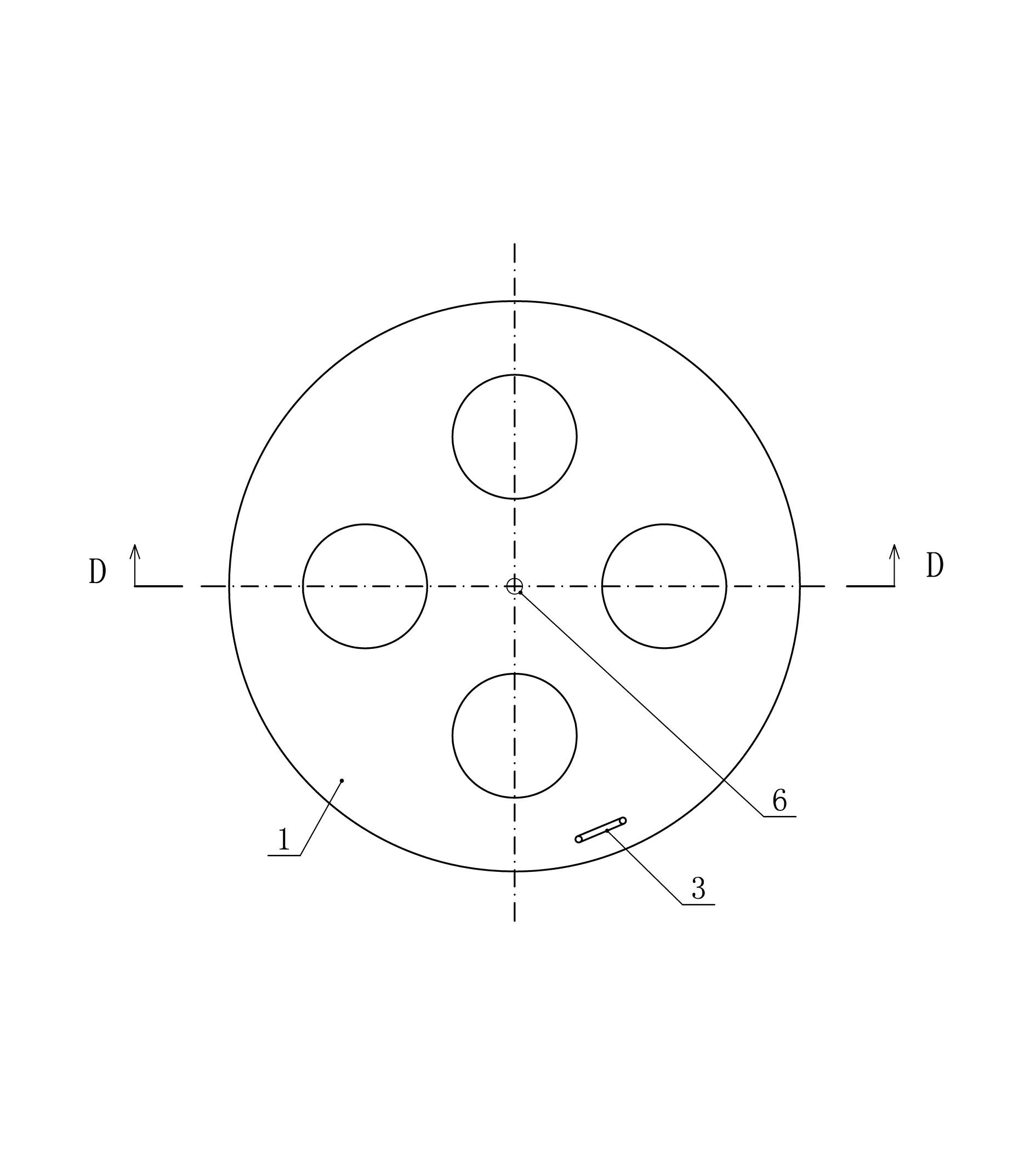
[0021] The present invention as figure 1 As shown, a floor-standing pay-off frame includes a fixed disc 1, which is characterized in that: the center of the fixed disc 1 is a fixed coil shaft 6, the fixed disc 1 is sleeved with a roller 2, and the center of the roller 2 is a roller The tube shaft 5, the rolling tube shaft 5 is sleeved on the fixed coil tube shaft 6, the fixed disc 1 is welded by the fixed coil tube shaft 6 and the circular steel plate 9, and the rolling plate 2 is made of the rolling tube tube shaft 5 and the channel steel 8 Made by welding. According to the floor pay-off stand, it is characterized in that: the tail end of the channel steel 8 is welded with a roller steel plate 7, and the roller steel plate 7 is equipped with a roller 4. According to the floor pay-off stand, it is characterized in that: the rolling plate 2 is surro...


PUM


Abstract

The invention discloses a ground pay-off rack which comprises a fixed disk, a fixed disk pipe shaft arranged in the center of circle of the fixed disk, a roller disk nested in the fixed disk, and a roller disk pipe shaft arranged in the center of circle of the fixed disk, wherein the fixed disk is formed by welding the fixed disk pipe shaft and a round steel plate and the roller disk is formed by welding the roller disk pipe shaft with channel steel. The ground pay-off rack is used for paying off ground wires. During construction, a wire carrier is put on the ground pay-off rack and then paid off without a wire unlading vehicle. The ground pay-off rack is suitable for a narrow construction space where the vertical pay-off rack can not be laid.

Description

technical field [0001] The invention relates to a bracket for laying out wires, ground wires and cables in electric power engineering construction, in particular to a floor-standing wire-laying rack. Background technique [0002] In the construction of electric power engineering, when laying out wires, ground wires and cables, lay the wire reel on the floor pay-off reel to lay out the wires. There are a lot of inconveniences in the existing tools, and the purpose cannot be well realized. Contents of the invention [0003] The object of the present invention is to provide a floor wire pay-off frame that can be used to pay out wires in places with narrow spaces. [0004] To achieve the above object, the technical solution adopted in the present invention is: [0005] A floor-standing pay-off stand, including a fixed disc, characterized in that: the center of the fixed disc is a fixed coil shaft, the fixed disc is sleeved with a rolling disc, the center of the rolling disc ...

Claims


Application Information

Patent Timeline
IPC IPC(8): B65H49/32B65H49/18
Inventor 严志敬张恩锋张先贵翟福军张丰仁张浩王涛程应顺孙秀芹王正刚刘鹏史永辉杨启星郭斌庞静孙卓辉孟凡民高飞孙权徐鸣
Owner 枣庄矿业(集团)有限责任公司供电工程处
Learn More