Water Hose Positioning Device

Inactive Publication Date: 2010-03-11
MCCLANAHAN GEORGE H +1
View PDF26 Cites 1 Cited by
  • Summary
  • Abstract
  • Description
  • Claims
  • Application Information

AI Technical Summary

Benefits of technology

[0006]Therefore, a general object of this invention is to provide a water hose end positioning device for protecting the hose end from damage.
[0007]Another object of this invention is to provide a water hose end positioning device, as a

Problems solved by technology

Garden hoses are subject to damage when attached to a spigot.
Specifically, tugging too vigorously on an attached hose end may cause the threads on the end of the hose to become bent or for the hose to actually weaken or tear.
In either case, the fragile end of the

Method used


Image

  • Water Hose Positioning Device
  • Water Hose Positioning Device
  • Water Hose Positioning Device

Examples


Example

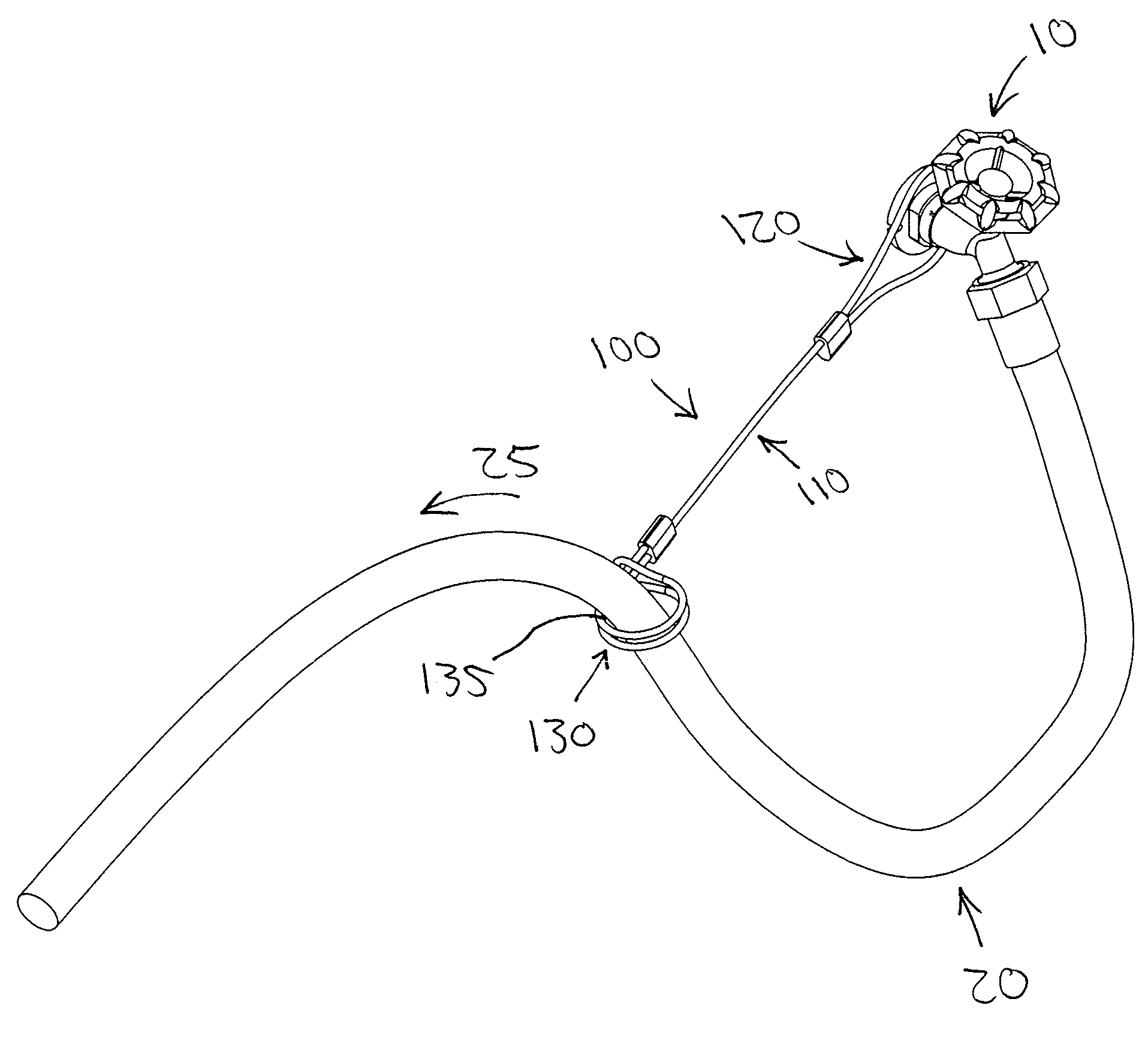
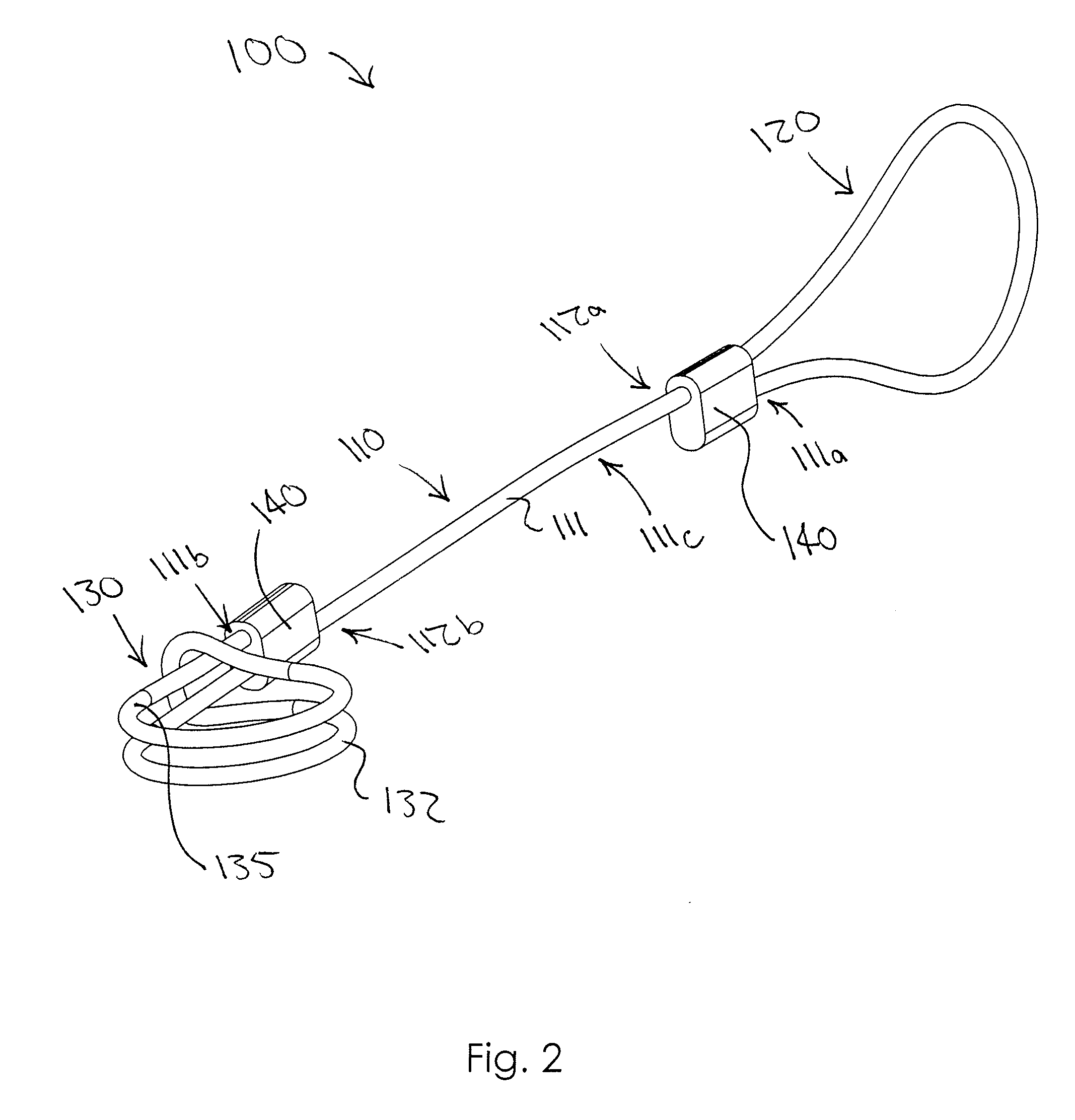
[0014]A water hose positioning device will now be described in detail with reference to FIG. 1 through FIG. 4 of the accompanying drawings. More particularly, a water hose positioning device 100 includes an elongate length element 110 and two loops 120, 130.

[0015]As shown in FIGS. 2, the elongate length element 110 has opposed ends 112a, 112b and may be flexible. In some embodiments, at least one flexible cable 111 forms the length element 110. Appropriate flexible cables 111 include, for example, braided stainless steel cables, flexible molded plastic straps, flexible extruded plastic straps, and other metal and non-metal cables.

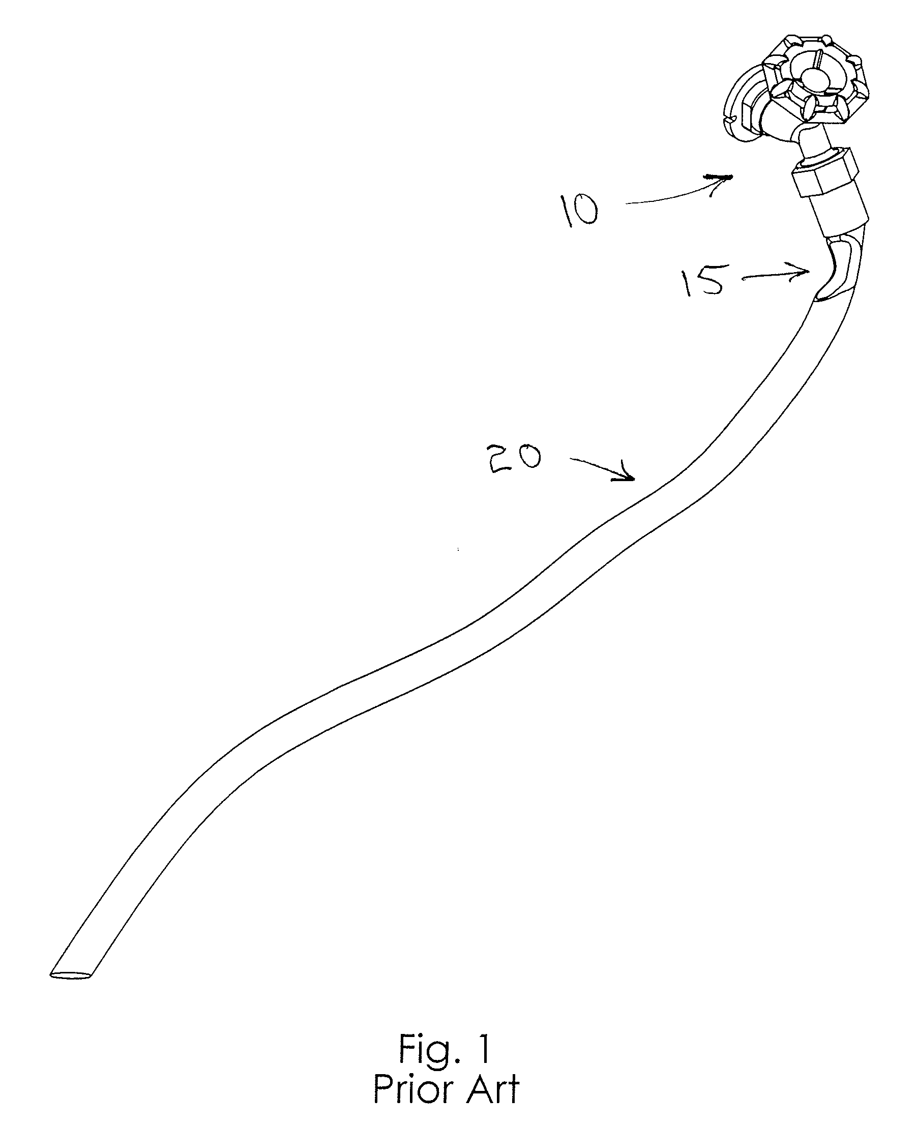
[0016]The loop 120 is at the end 112a of the length element 110 and is configured to be coupled to a spigot 10, as shown in FIG. 3. As shown in FIG. 2, the flexible cable 111 that forms the length element 110 may also form the loop 120. More particularly, the flexible cable 111 may include first and second ends 111a, 111b and have an intermediate section 11...


PUM


Abstract

A water hose end positioning device according to the present invention includes a first loop configured to be coupled to a spigot. An adjustable loop is configured to encircle a portion of a water hose coupled to the spigot and to contract when the portion of said water hose is under tension to inhibit the water hose from kinking between the adjustable loop and the spigot. The positioning device includes a flexible elongate length element extending between the first loop and the adjustable loop.

Description

BACKGROUND OF THE INVENTION[0001]This invention relates generally to hose accessories and, more particularly, to a water hose positioning device that maintains an end of a garden hose in a straight and stabilized configuration when attached to a spigot so as to prevent damage to the hose end.[0002]Garden hoses are subject to damage when attached to a spigot. Specifically, tugging too vigorously on an attached hose end may cause the threads on the end of the hose to become bent or for the hose to actually weaken or tear. Pressure exerted upon an attached hose end may be the result of a user trying to stretch the hose to its maximum length from the spigot or because a user is attempting to shake kinks from the hose. In either case, the fragile end of the hose is frequently damaged during normal use.[0003]Various devices have been proposed in the art for holding a hose in a storage configuration or even for holding a hose accessory, such as a sprayer, when not in use. Although assumabl...

Claims


Application Information

Patent Timeline
IPC IPC(8): B05B15/06
CPCF16L3/003
Inventor MCCLANAHAN, GEORGE H.MCCLANAHAN, JEFFERY
Owner MCCLANAHAN GEORGE H
Why Eureka
Try Eureka