
System for installing chains on vehicle tires

Inactive Publication Date: 2007-01-23
LYNE JR ROBERT C
View PDF12 Cites 9 Cited by
  • Summary
  • Abstract
  • Description
  • Claims
  • Application Information

AI Technical Summary

Benefits of technology

[0025]The system also utilizes a tray-like device in which the tire chain and the tool are arranged, and may be stored, in a partially laid-out orientation prior to installation. This device, which performs the function of the ramps and chain caddy referred to above, will be referred to hereinafter as an “installation tray” or “tray”. The installation tray has longitudinal channels and transverse channels for holding laid-out side chains and cross chains, respectively, and a well for holding side chains and cross chains which are not laid out. The installation tray also has a compartment adjacent the well for holding the tool and protecting it from damage due to the weight of the vehicle.
[0026]The method of installing the tire chain is as follows. The untwisted tire chain is arranged in the tray with the tool connected to it, as described above. The vehicle is driven onto the tray and stopped when the vehicle is in a predetermined, optimum position with respect to the tray and chain. Holding the handle, the user picks up the tool and draws it, with one end of the tire chain trailing it, upward and circumferentially around the tire. With the tool straddling the tire so that its handle bridges the tread of the tire and its arms extend along the opposite sidewalls, the tire chain is disposed and tensioned substantially in its correct position on the tire. The fastening element at the other, free end of each side chain is then brought up and connected to the mating fastening element. The connection of the side chain elements on the inner sidewall may be made while the tool is still connected to the fastening element, which enables the arm of the tool on the inner sidewall to be used to guide the free element into contact and connection with the element connected to the tool. In most cases this eliminates the need for the user to see the two elements being connected and the need to hold the two elements with both hands simultaneously, so that the user does not need to lie on the ground. After the tool is disconnected from the chain, the vehicle is driven off the tray.
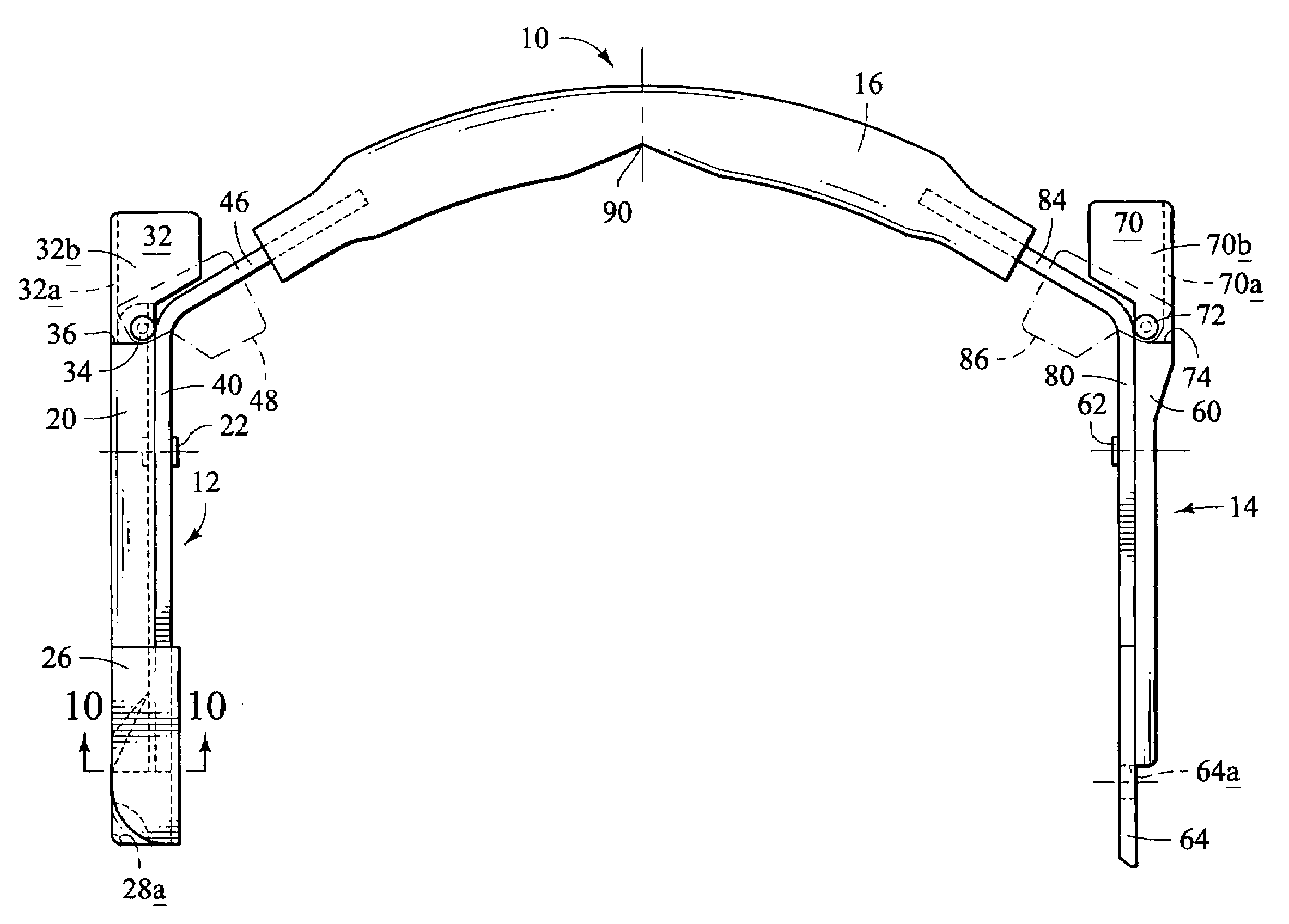
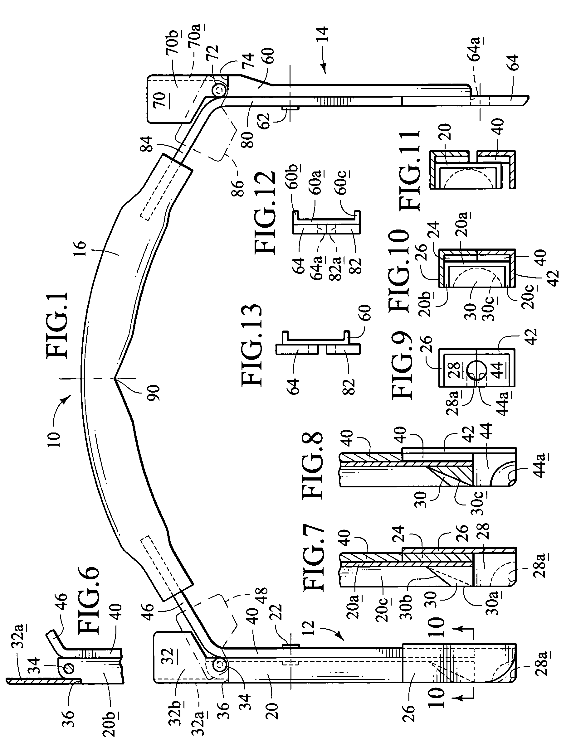
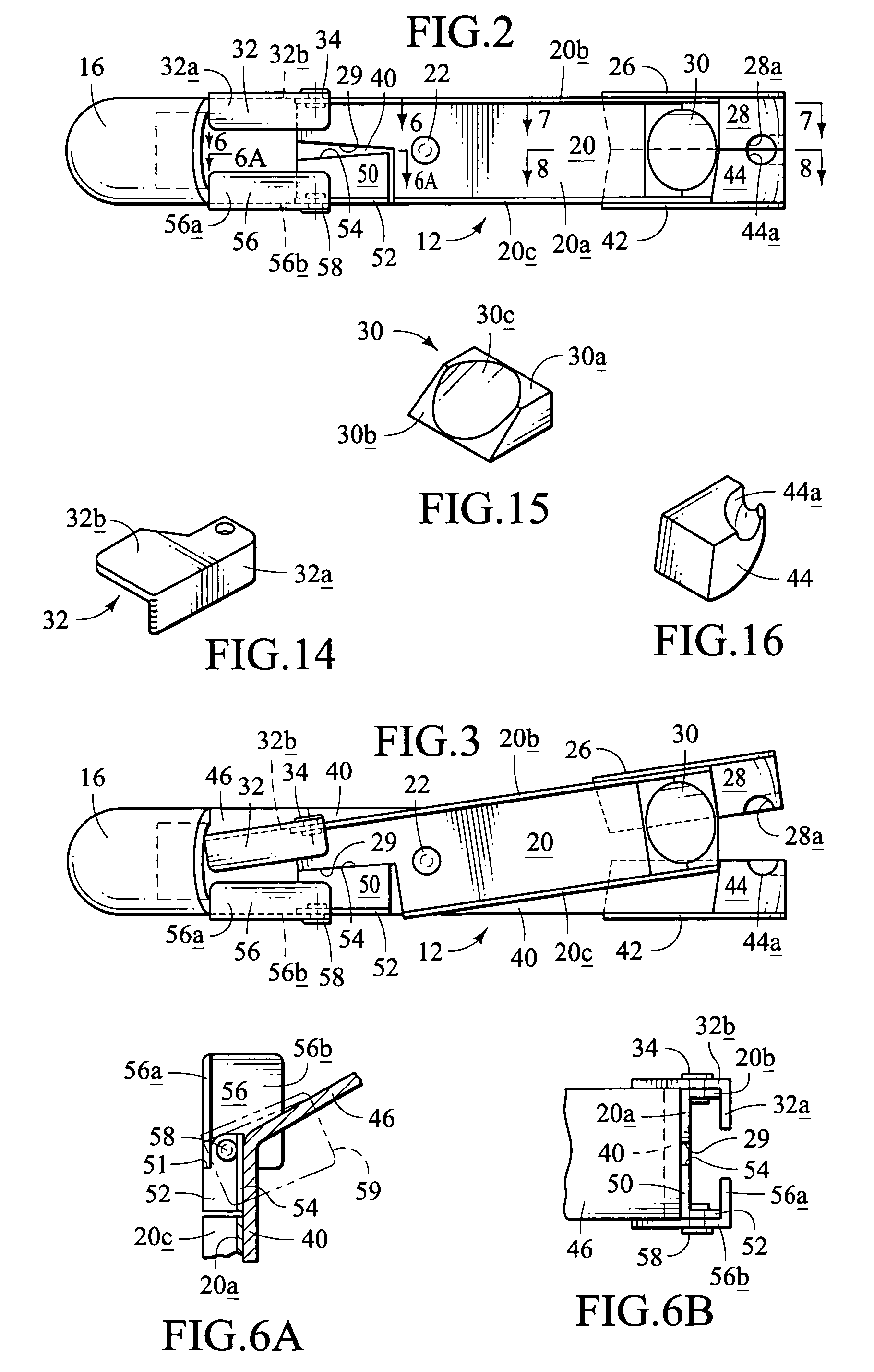
[0027]The system according to the invention may include additional features. The inner arm of the tool may have flanges defining a channel for guiding the free fastening element into proximity and contact with the fastening element held by that arm. An inclined ramp-like surface may be disposed in that channel. The tray may have slots for locating and restraining the free fastening elements, and stacking lugs and recesses to permit a plurality of trays to be stacked during storage. A device may be provided in a recess in the tray to sense the position of the tire and initiate a signal to stop the vehicle. The position of the signal-initiating device relative to the transverse channels in the tray may be adjustable. Preferably the signal issues when, and only when, the tire is positioned within a predetermined theoretical zone defined by boundaries spaced along the longitudinal axis of the tray, so that the device is able to sense and signal the stopped position of the tire as well as the position of the tire while it is still moving. The chain elements held by the arms of the tool may be released therefrom by the action of a readily accessible latch or similar locking device under the control of and actuated by the user. Force for opening the claws of the tool may be applied to the open latch. The handle of the tool may be articulated to permit the claws of the two arms, and the elements of the chain they hold, to be brought close to each other. The tool may have features which enable it to be easily adapted and used for tires of different sizes.

Problems solved by technology

Also known are the disadvantages of tire chains, which, assuming well designed chains are properly selected for a given vehicle, tend to fall into three categories.
The disadvantages within this category include the considerable time required for installation and the physical difficulty and discomfort involved, often under adverse weather conditions, darkness, or stress.
The second category of disadvantages is operation of the vehicle after the chains have been installed.
These disadvantages include chain wear and breakage, limitations on vehicle speed, vibration and accelerated wear of the vehicle, possible damage to the vehicle resulting from breakage of worn chains, and damage to the pavement.
These disadvantages are greatly amplified by operation of the vehicle on bare pavement.
These three categories of disadvantages are directly related, in that solutions to installation and removal problems ameliorate problems during vehicle operation.
That is, if tire chains could be installed instantly by a mere snap of the driver's fingers immediately before serious snow or ice are encountered, and removed in the same manner when no longer needed, their above-mentioned operating disadvantages would disappear.
A problem presented by ramps is the difficulty of stopping the vehicle at the desired position on the ramp.
This approach is not always effective, because under actual conditions it is difficult for the driver to feel the stop through the vehicle and distinguish it from other bumps, and he or she may drive the vehicle over the stop.
The hoop makes the tire chain difficult to store and handle and may require extensive manipulation of the tire chain under and on the sidewalls of the tire.
The hoop also makes removal of the tire chain more difficult.

Method used


Image

  • System for installing chains on vehicle tires
  • System for installing chains on vehicle tires
  • System for installing chains on vehicle tires

Examples


Embodiment Construction

Definitions

[0070]The following terms will be used throughout this application in accordance with these definitions, unless a different interpretation is required by the context.

[0071]The term “tire” refers to an inflated tire mounted on a rim which is a component of a wheel on a vehicle. The tire has a tread which joins 2 sidewalls—an “inner” sidewall toward the shaft driving the wheel and an opposite, “outer” sidewall. The terms “inner” and “outer” will be used in a similar manner to refer to an arm of the tool intended to be used adjacent a sidewall. The “width” of the tread is the distance between its edges, in the direction parallel to the axis of rotation of the wheel. The “maximum width” or “section width” of the tire is its maximum width in a direction parallel to the wheel's axis of rotation and is conventionally the nominal width of the tire. The “radius” of the tire is the distance from the axis of rotation to the ground. The “footprint” of the tire is the portion of its t...


PUM

PropertyMeasurementUnit
Forceaaaaaaaaaa
Heightaaaaaaaaaa
Distanceaaaaaaaaaa

Abstract

A drive-on system for installing a tire chain (i.e., snow chain) on a pneumatic tire mounted on a vehicle wheel. The system includes a U-shaped installation tool whose arms releasably engage fastening elements (hooks or links) at one end of each side chain, and a installation tray or ramp in which the connected tire chain and tool are arranged, and may be stored, prior to installation, with the tire chain in a partially laid-out orientation and the tool preferably within a tool compartment in the tray. To install the tire chain, the vehicle is driven onto the tray and stopped, preferably in a predetermined optimum position in response to a signal initiated by a position-indicating switch on the tray. Then the tool, with one end of the tire chain connected to it and trailing it, is drawn upward and circumferentially around the tire. With the tool bridging the tread of the tire so that its arms extend along the opposite sidewalls, the tire chain is draped and tensioned substantially in the correct position on the tire. The fastening element at the other, free end of each side chain is then removed from its place in the tray and connected to the mating fastening element. The connection on the inner sidewall is preferably made while the tool is still connected, which enables the arm of the tool on the inner sidewall to be used to guide the free element into contact and connection with the element connected to the tool.

Description

RELATED APPLICATIONS[0001]This application is a division of application Ser. No. 10 / 241,968 filed Sep. 12, 2002 and now issued as U.S. Pat. No. 6,681,657. Application Ser. No. 10 / 241,968 is a continuation of application Ser. No. 09 / 879,629 filed Jun. 12, 2001 now abandoned. Application Ser. No. 09 / 879,629 was copending with and a continuation-in-part of application Ser. No. 09 / 471,664 filed Dec. 24, 1999 and now issued as U.S. Pat. No. 6,263,554. Application Ser. No. 09 / 471,664 was copending with and a continuation-in-part of application Ser. No. 09 / 033,886 filed Mar. 3, 1998 and now abandoned. Application Ser. No. 09 / 033,886 was copending with provisional patent application Ser. No. 60 / 039,794, filed Mar. 4, 1997. Each of those five earlier applications is titled “System for Installing Chains on Vehicle Tires”. This application discloses and claims subject matter disclosed in the five earlier applications and relies on them under 35 U.S.C. 120. The disclosures of the five earlier a...

Claims


Application Information

Patent Timeline
IPC IPC(8): B60C27/06B25B27/22
CPCB25B27/22Y10T29/53Y10T29/49764Y10T29/53961Y10T29/49778
Inventor LYNE, JR., ROBERT C.
Owner LYNE JR ROBERT C
Learn More