Ultrasonic transducer for use in a fluid medium

Inactive Publication Date: 2012-02-16
ROBERT BOSCH GMBH
View PDF12 Cites 13 Cited by
  • Summary
  • Abstract
  • Description
  • Claims
  • Application Information

AI Technical Summary

Benefits of technology

[0022]The ultrasonic transducer proposed above and corresponding methods for manufacturing such an ultrasonic transducer have a large number of advantages compared to known ultrasonic transducers and known methods. The matching of the coefficients of thermal expansion via the compensating body brings it about either that there occurs, at least to a large extent, no thermally induced mechanical stress between the piezoelectric transducer element and the material directly adjacent, in this case the compensating body, or else that the stress is much less than that between the compensating body and the immediately adjoining matching body. Thus, the sensitive piezoelectric transducer element is protected from damage, such as formation of microcracks and/or depolarization, which would often occur as a result of temperature shocks if the compensating body were not present. In addition, due to the homogeneity characteristic of the compensating body, this compensating body can be made relatively thick compared to non-homogenous materials such as fiber meshes. This means that the larger portion, or the entire CTE mismatch, can be positioned spatially far away from the piezoelectric transducer element, so that lower stresses also occur in the area of the piezoelectric transducer element.
[0023]In addition, the selection of a homogenous compensating body, instead of for example a fibroid intermediate layer, can remove the difficulty of positioning a fiber mat directly on the piezoelectric transducer element and holding it there until hardening takes place. Moreover, when fibers are installed, their stability generally depends, in a sensitive manner, on the fabric structure and the weave. If, in contrast,

Problems solved by technology

In known ultrasonic transducers, the connection between the matching body and the piezoelectric transducer element presents a particular technical challenge.
In particular in the area of the connection, temperature shocks can cause damages that are due to different coefficients of thermal expansion (CTE).
Such stresses occur due to a rather slow relaxation of tension, in particular when there are rapid temperature shocks.
However, as a rule such flexibilized adhesives become so flexible at higher temperatures that they are no longer a

Method used


Image

  • Ultrasonic transducer for use in a fluid medium
  • Ultrasonic transducer for use in a fluid medium
  • Ultrasonic transducer for use in a fluid medium

Examples


Example

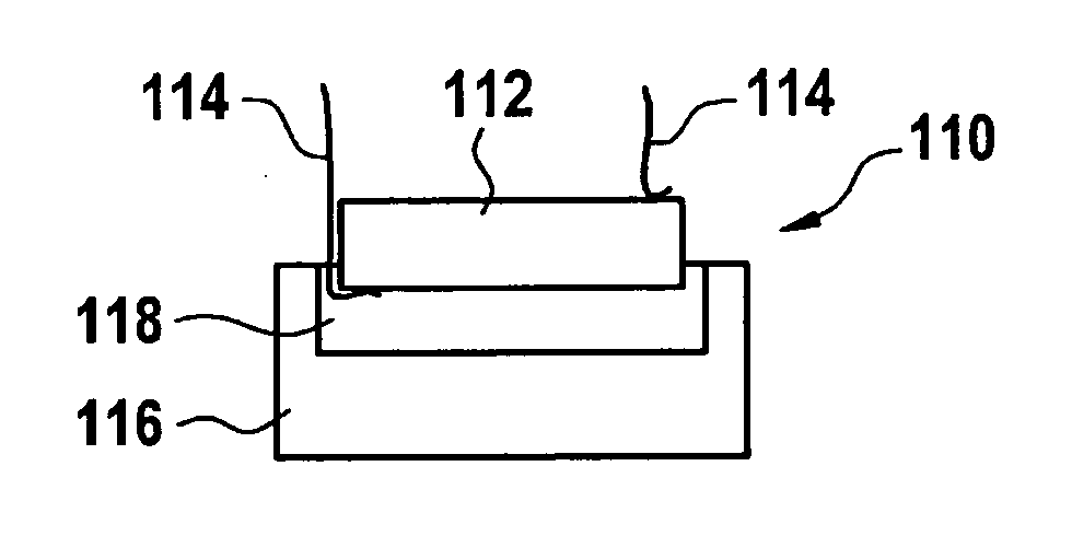
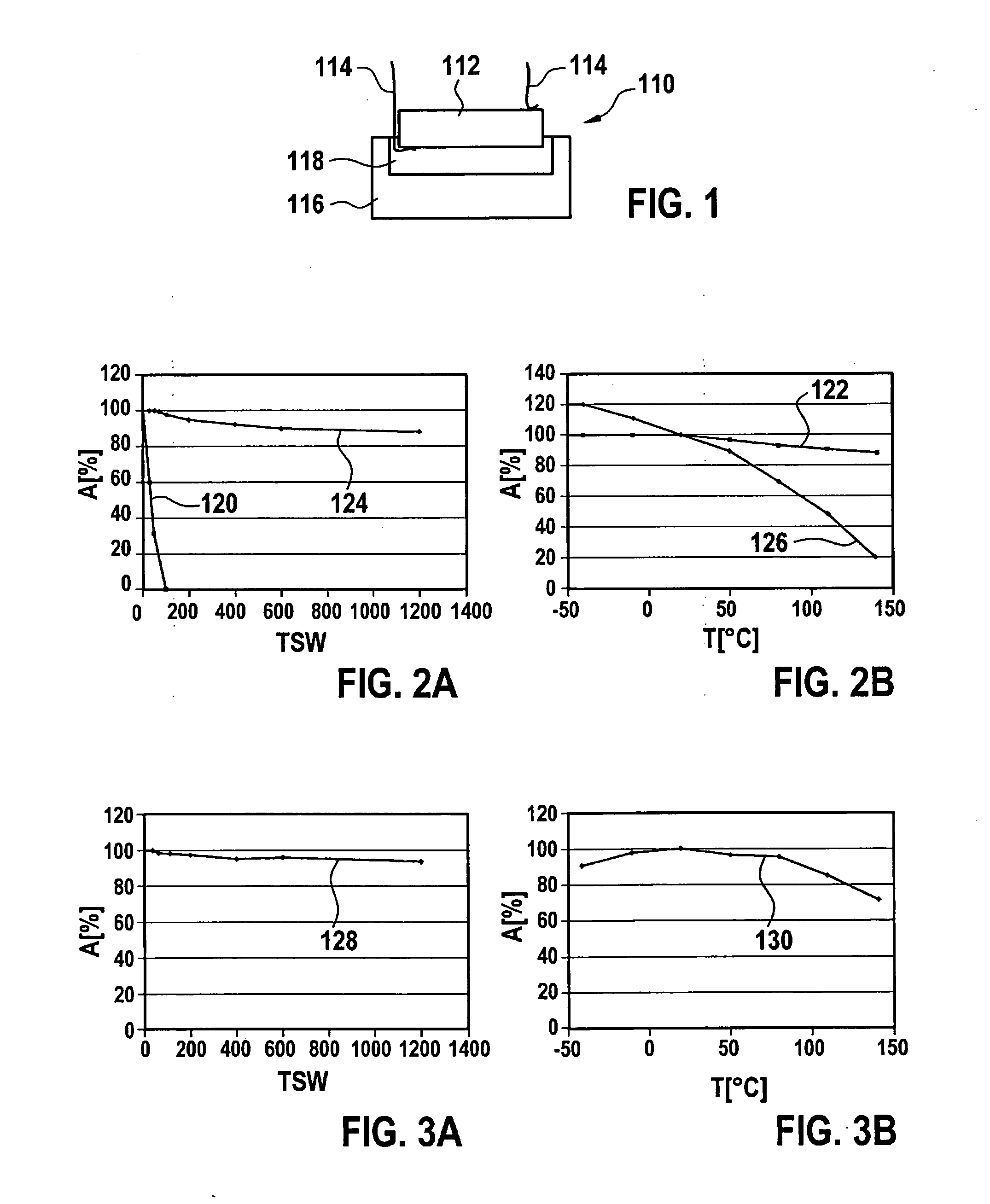
[0031]FIG. 1 shows a first exemplary embodiment of an ultrasonic transducer 110 according to the present invention in a sectional view from the side. Ultrasonic transducer 110 has a piezoelectric transducer element 112 that can be formed for example as a cylindrical piezoelement. This piezoelectric transducer element 112 can for example be electrically contacted via two terminal contacts 114, for example contact wires, so that piezoelectric transducer element 112 can for example be provided with control signals via these terminal contacts 114, and / or so that signals of the piezoelectric transducer element 112 can be led away via terminal contacts 114.

[0032]In addition, in the embodiment shown in FIG. 1 ultrasonic transducer 110 has a matching body 116. This matching body 116 is used to improve the vibrational coupling between piezoelectric transducer element 112 and a fluid medium into which ultrasonic signals are to be coupled and / or from which ultrasonic signals are to be coupled ...


PUM

PropertyMeasurementUnit
Thicknessaaaaaaaaaa
Temperature coefficient of resistanceaaaaaaaaaa
Hardeningaaaaaaaaaa

Abstract

An ultrasonic transducer for use in a fluid medium includes at least one piezoelectric transducer element, at least one matching body for the promotion of a vibrational coupling between the piezoelectric transducer element and the fluid medium, and at least one compensating body situated between the piezoelectric transducer element and the matching body for the reduction of thermal stresses, the compensating body having a coefficient of thermal expansion that is between a coefficient of thermal expansion of the piezoelectric transducer element and a coefficient of thermal expansion of the matching body.

Description

BACKGROUND OF THE INVENTION[0001]1. Field of the Invention[0002]The present invention relates to ultrasonic transducer for use in a fluid medium.[0003]2. Description of Related Art[0004]The present invention is based on known ultrasonic transducers that can be used for example in ultrasonic flow meters in process technology or in the automotive field, in particular in the intake and / or exhaust section of internal combustion engines, for volume flow or mass flow measurement. In this context, typically ultrasonic transducers are used that are capable both of emitting ultrasonic waves into a fluid medium (a gas and / or a liquid) and also receiving ultrasonic waves. Standardly, ultrasonic signals are transmitted through the flowing fluid medium from a transmitter to a receiver, and the runtime, runtime differences, or phases of the ultrasonic signals, or also combinations of these measurement quantities, are measured during this transmission. These signals are influenced by the flow of t...

Claims


Application Information

Patent Timeline
IPC IPC(8): G10K9/122H04R31/00
CPCG01F1/662G01F1/667G10K11/02Y10T29/49005
Inventor MUELLER, ROLANDHUEFTLE, GERHARDHORSTBRINK, MICHAELLANG, TOBIASRADWAN, SAMIKUENZL, BERNDWANJA, ROLAND
Owner ROBERT BOSCH GMBH
Why Eureka
Try Eureka