Slip seal retainer and stop

Inactive Publication Date: 2005-01-11
ARVINMERITOR TECH
View PDF15 Cites 10 Cited by
  • Summary
  • Abstract
  • Description
  • Claims
  • Application Information

AI Technical Summary

Benefits of technology

The placement of the cover over the seal and a substantial portion of the outer surface of a sealing portion prevents the seal from expanding, becoming dislodged or being deformed during use. The cover therefore maintains the seal in proper engagement with the end of the slip yoke. Further, the substantially rigid cover protects the seal from being damaged by contact with debris during operation.
The cover includes an axially extended stop portion which is of an axial length to provide contact with a flange of a splined shaft prior to an end of the splines shaft contacting a plug. The stop portion defines the minimum leng

Problems solved by technology

In some instances, the splined shaft may be inadvertently collapsed past a designed minimum length during shipping

Method used


Image

  • Slip seal retainer and stop
  • Slip seal retainer and stop
  • Slip seal retainer and stop

Examples


Example

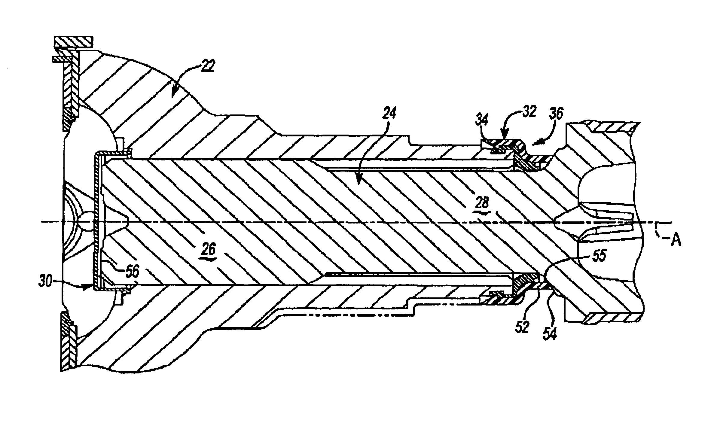
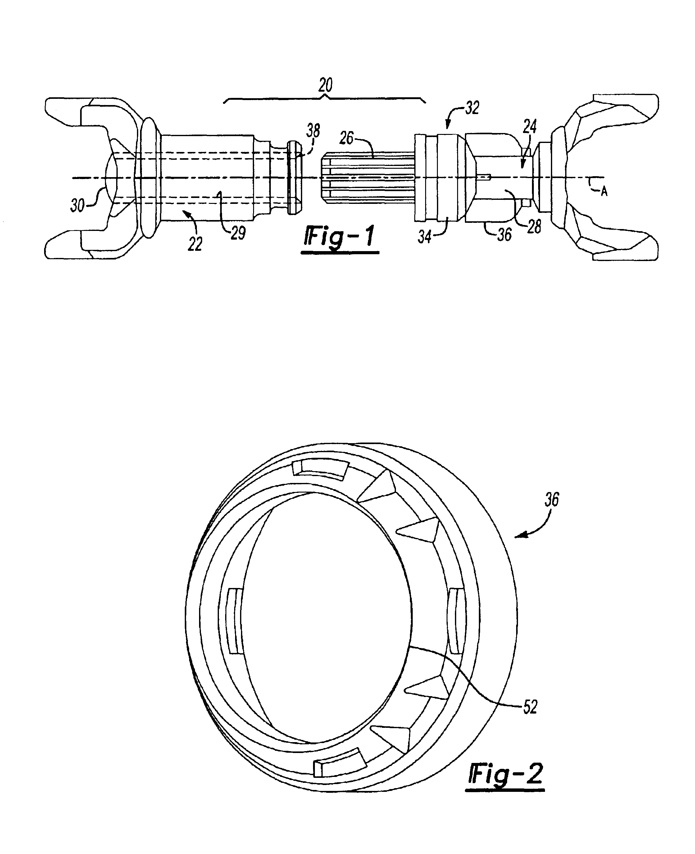
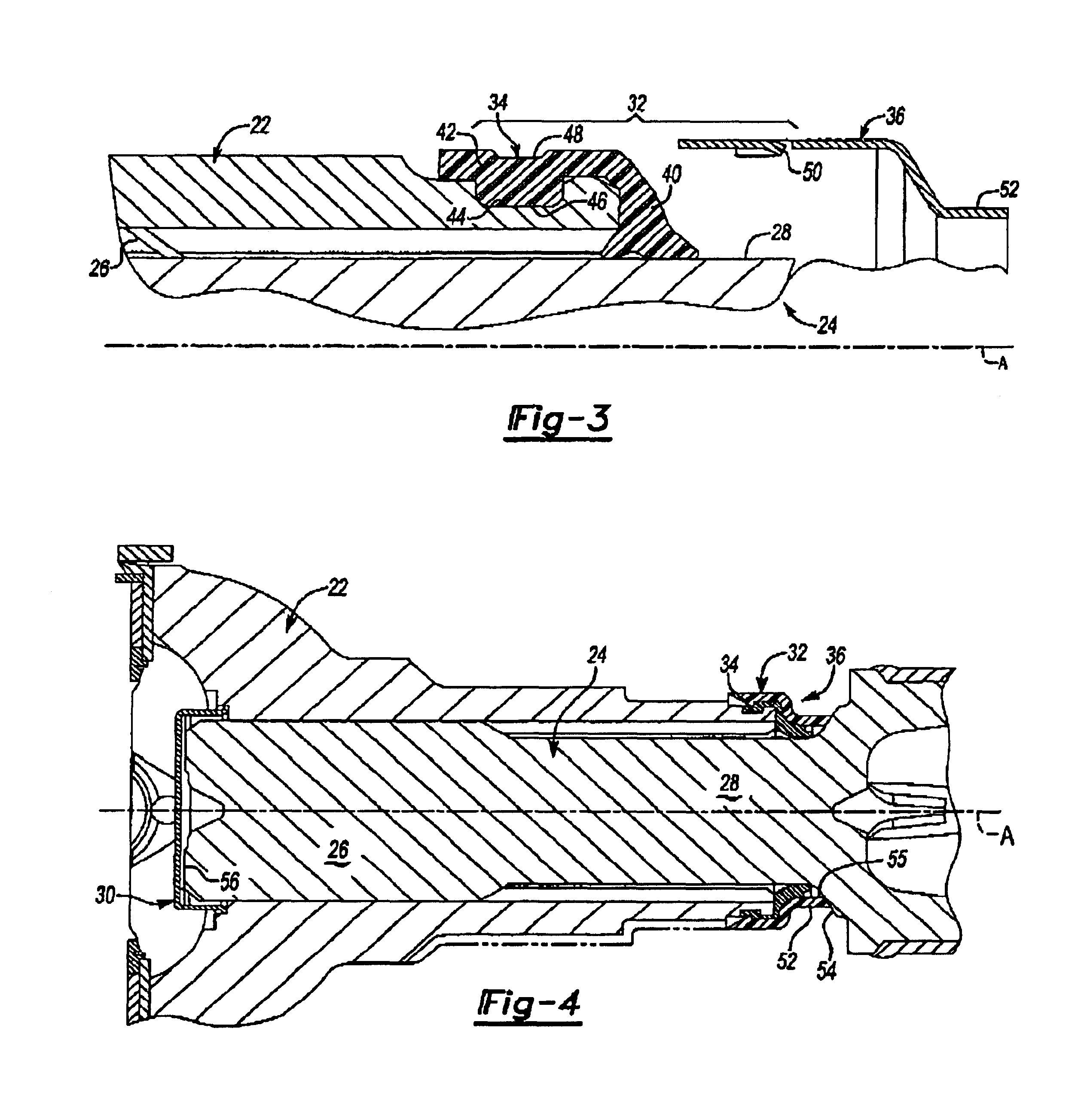
FIG. 1 illustrates a general perspective view of a slip shaft drive assembly 20 that includes a slip yoke 22 and a splined shaft 24. The shaft 24 includes a splined portion 26 and a neck portion 28. The outer diameter of the splined portion 26 is greater than the outer diameter of the neck portion 28. The shaft 24 is received within a central bore 29, which extends axially through the slip yoke 22. The shaft 24 is slidably received within the bore 29 such that the shaft 24 can move axially along axis A relative to the slip yoke 22. Lubricant preferably is placed within the bore 29 to facilitate the relative axial movement between the shaft 24 and the yoke 22.

A sealing plug 30 is provided at one end of the slip yoke 22. The sealing plug 30 contains the lubricant within the bore 29 of slip yoke 22. The sealing plug 30 may be removed prior to vehicle installation or left in place depending upon the shaft drive assembly 20. Moreover, the plug 30 and a sealing assembly 32 allows for rela...


PUM


Abstract

A sealing assembly for a slip shaft drive assembly includes a generally resilient seal and a substantially rigid cover which is mounted at an end of a slip yoke. The cover includes an axially extended stop portion which is of an axial length to provide contact with a flange of a splined shaft prior to an end of the splined shaft contacting a plug. The stop portion defines the minimum length to which the slip shaft drive assembly may be collapsed and thereby eliminates the possibility of the plug being dislodged during shipping and/or handling.

Description

BACKGROUND OF THE INVENTIONThe present invention relates to a slip shaft driveline assembly, and more particularly to a cover that protects a seal for closing one end of a driveline slip yoke and operates as a stop during shipping.Drive trains for use in heavy-duty applications often include a slip yoke connection for connecting a splined shaft to a universal joint. A conventional slip yoke includes a central, longitudinal bore that receives a splined portion on a connection shaft. The splined shaft typically moves axially within the slip yoke bore. Lubricant is provided within the slip yoke bore to facilitate the relative axial movement between the splined shaft and the slip yoke. Each end of the slip yoke bore is preferably sealed to maintain the lubricant within the bore and to prevent undesirable contaminants from entering the bore. One end of the slip yoke bore can be plugged. The other end, however, requires a sealing arrangement that seals the moving splined shaft as it moves...

Claims


Application Information

Patent Timeline
IPC IPC(8): F16D3/38F16D3/16
CPCF16D3/387F16C3/03F16C29/08F16D3/06F16D3/40F16D3/848
Inventor LENTINI, ANTHONY G.KONIOR, WILLIAM A.BRISSETTE, RONALD N.
Owner ARVINMERITOR TECH
Why Eureka
Try Eureka