Method and apparatus for controlling carrier envelope phase

a carrier envelope and phase control technology, applied in electrical devices, wave amplification devices, laser details, etc., can solve the problems of limiting feedback bandwidth, interfering with the output of the cpa laser system, and the output power of the oscillator

Inactive Publication Date: 2010-03-11
KANSAS STATE UNIV RES FOUND
View PDF5 Cites 20 Cited by
  • Summary
  • Abstract
  • Description
  • Claims
  • Application Information

AI Technical Summary

Benefits of technology

[0008]In various embodiments the present invention provides a chirped pulse amplification laser system that comprises a laser source, a pulse modification apparatus including first and second pulse modification elements separated by a separation distance, a positioning element, a measurement device, and a feedback controller. The laser source is operable to generate a laser pulse and the pulse modification apparatus operable to modify at least a portion of the laser pulse. The positioning element is operable to reposition at least a portion of the pulse modification apparatus to vary the separation distance. The measurement device is operable to measure the carrier envelope phase of the generated laser pulse and the feedback controller is operable to control the positioning element based on the measured carrier envelope phase to vary the separation distance of the pulse modification elements and control the carrier envelope phase of at least one laser pulse generated by the laser source.

Problems solved by technology

Unfortunately, adding a feedback loop to an oscillator may disturb the oscillator's output power and limit feedback bandwidth, thereby interfering with the output of the CPA laser system.

Method used


Image

  • Method and apparatus for controlling carrier envelope phase
  • Method and apparatus for controlling carrier envelope phase
  • Method and apparatus for controlling carrier envelope phase

Examples


Embodiment Construction

[0019]The following detailed description of various embodiments of the invention references the accompanying drawings which illustrate specific embodiments in which the invention can be practiced. The embodiments are intended to describe aspects of the invention in sufficient detail to enable those skilled in the art to practice the invention. Other embodiments can be utilized and changes can be made without departing from the scope of the present invention. The following detailed description is, therefore, not to be taken in a limiting sense. The scope of the present invention is defined only by the appended claims, along with the full scope of equivalents to which such claims are entitled.

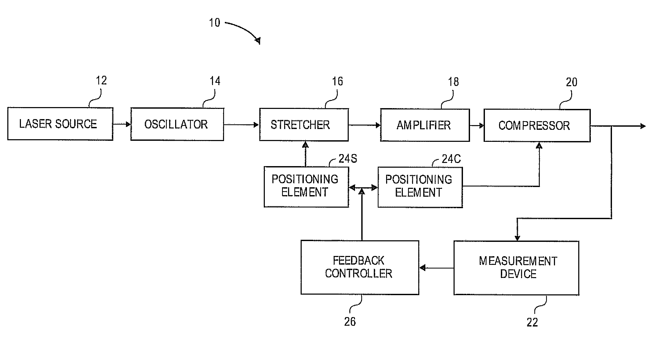
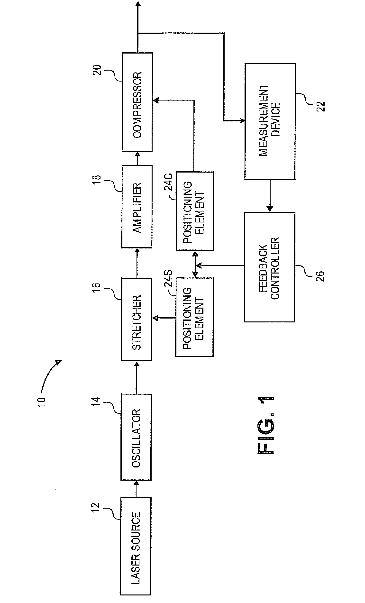
[0020]Various embodiments of the present invention utilize a laser system 10 as illustrated in FIG. 1. In some embodiments, the laser system 10 is configured as a chirped pulse amplification (CPA) laser system that includes a pulse modification apparatus operable to stretch and / or compress a lase...


PUM


Abstract

A chirped pulse amplification laser system. The system generally comprises a laser source, a pulse modification apparatus including first and second pulse modification elements separated by a separation distance, a positioning element, a measurement device, and a feedback controller. The laser source is operable to generate a laser pulse and the pulse modification apparatus operable to modify at least a portion of the laser pulse. The positioning element is operable to reposition at least a portion of the pulse modification apparatus to vary the separation distance. The measurement device is operable to measure the carrier envelope phase of the generated laser pulse and the feedback controller is operable to control the positioning element based on the measured carrier envelope phase to vary the separation distance of the pulse modification elements and control the carrier envelope phase of laser pulses generated by the laser source.

Description

RELATED APPLICATION[0001]The present non-provisional application claims the benefit of U.S. Provisional Application No. 60 / 805,717, entitled “STABILIZATION OF CARRIER ENVELOPE PHASE BY FEEDBACK CONTROLLING GRATING SEPARATION,” filed Jun. 23, 2006. The identified provisional application is incorporated herein by specific reference.FEDERALLY SPONSORED RESEARCH OR DEVELOPMENT PROGRAM[0002]The present invention was developed with support from the U.S. government under Grant No. DE-FG02-86ER13491 awarded by the Department of Energy and Grant No. 0457269 awarded by the National Science Foundation. Accordingly, the U.S. government has certain rights in the present invention.BACKGROUND OF THE INVENTION[0003]1. Field of the Invention[0004]Embodiments of the present invention relate generally to methods and apparatuses for controlling carrier envelope phase. Particularly, various embodiments of the present invention provide methods and apparatuses for controlling carrier envelope phase by con...

Claims


Application Information

Patent Timeline
Patent Type & Authority Applications(United States)
IPC IPC(8): H01S3/13
CPCH01S2301/08H01S3/0057
Inventor CHANG, ZENGHULI, CHENGQUANMOON, ERIC
Owner KANSAS STATE UNIV RES FOUND
Why Eureka
Try Eureka