Support for a cpr apparatus

a technology of cpr and support, which is applied in the direction of artificial respiration, heart stimulation, therapy, etc., can solve the problems of cardiac arrest risk being lethal or at least severely disabilitating, and hitting anyone anywhere, so as to achieve the effect of convenient attachment and disassembly

Inactive Publication Date: 2010-03-11
JOLIFE AB
View PDF6 Cites 38 Cited by
  • Summary
  • Abstract
  • Description
  • Claims
  • Application Information

AI Technical Summary

Benefits of technology

[0011]According to a second preferred aspect of the invention the support frame comprises two inflatable legs and a back plate. The leg, which are preferably of about same size and form, extend from or are attached to opposite sides of the CPR apparatus, preferably in a mirroring manner. In this application the attached or extending ends are termed first ends. The other, second ends of the inflatable legs are releaseably mountable to and/or dismountable from the back plate. The back plate can be in one pieces or comprise two pieces of generally same shape, which can be easily attached to each other and dismounted.
[0012]According to a third preferred aspect of the invention the back plate comprises one or more inflatable elements, which may be inflatable separately from or in combination with the inflatable legs. It is preferred for the inflatable element(s) of the back plate to be integral with one or both legs; in such case it

Problems solved by technology

Cardiac arrest risks to be lethal or at least severely disabilitating if circulation and oxygenation of blood

Method used


Image

  • Support for a cpr apparatus
  • Support for a cpr apparatus
  • Support for a cpr apparatus

Examples


first embodiment

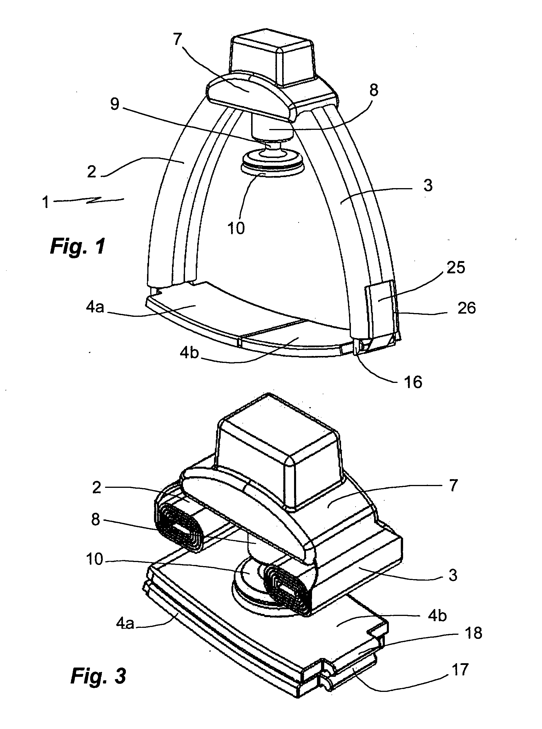
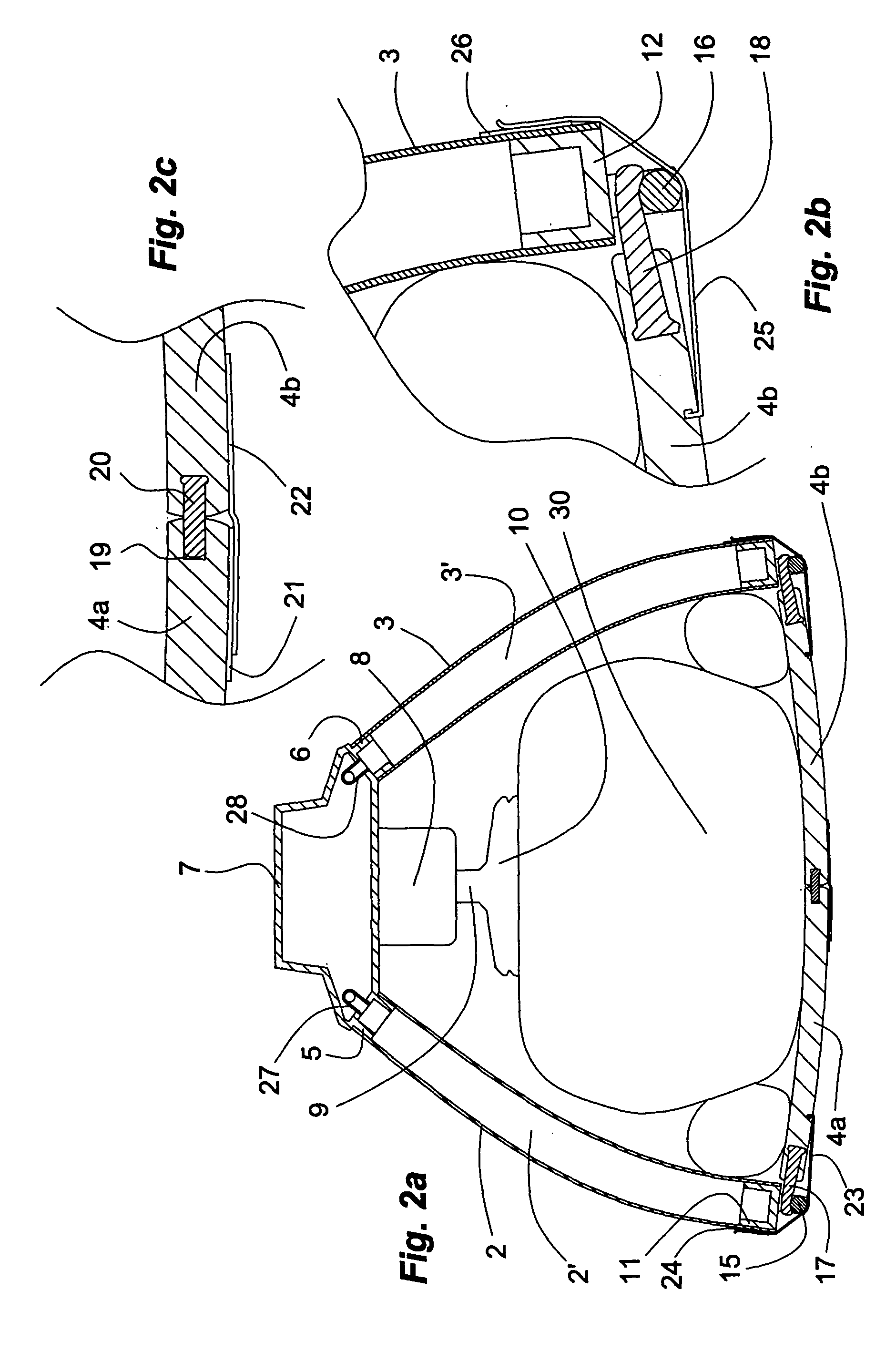
[0022]a CPR support frame 1 of the invention illustrated in FIGS. 1 and 2a-2c in a mounted state and in FIG. 3 in a dismounted state comprises two inflatable legs 2, 3 and a stiff back plate comprising two sections 4a, 4b that can be easily connected and disconnected. The legs 2, 3 are of flexible but substantially not extendable polymer material such as polyurethane reinforced by a mesh of nylon or the like. At their one, upper end, the legs 2, 3 are plugged on and sealingly fixed by gluing to connecting sleeve portions 5, 6 integral with and protruding from opposite sides of a CPR apparatus housing. The housing 7 is made of a stiff light weight material such as a magnesium alloy but a non-conducting polymer material is preferred to eliminate the risk of aberrant electrical conduction during defibrillation. A preferred material for the housing is glass fibre-reinforced polyamide. The CPR apparatus comprises a gas driven reciprocating piston mounted in a cylinder 8 from which the pi...

second embodiment

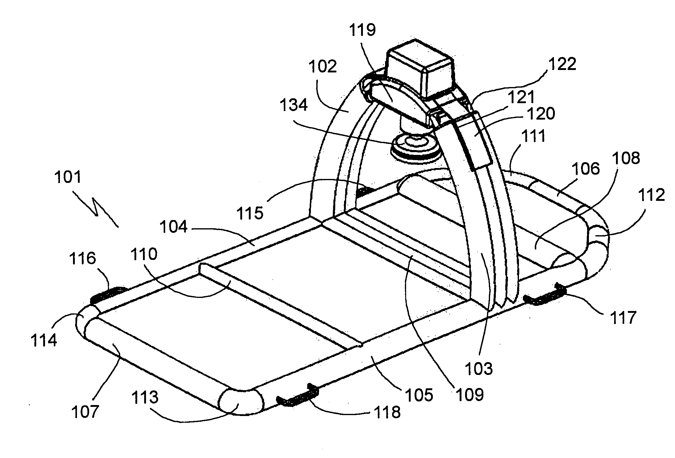
[0023]a CPR support frame 101 of the invention illustrated in FIG. 4 in a mounted state comprises two inflatable legs 102, 103 joined to a base of inflatable elements 104, 105, 106, 107, 108, 109, 110, 111, 112, 113, 114, the lumina of which are in communication with each other and with the lumina of the legs 102, 103. The base 104-114 is a generally flat structure also in the inflated state shown in FIG. 4. The base comprises a rectangular framing 104, 105, 106, 107 with rounded corner portions 111, 112, 113, 114. Reference numbers 104, 105 designate opposite long-side inflatable elements whereas reference numbers 106 and 107 designate opposite short-side inflatable elements. The long-side elements 104, 105 are additionally connected by bridging elements 108, 109, 110. The bridging element 109 connects the long-side elements 104, 105 at their portions from which the inflatable legs 102, 103 rise about perpendicularly above the base 104-114. The base 104-114 is so dimensioned that a...


PUM


Abstract

A support frame for a CPR apparatus, in particular a gas-driven CPR apparatus, comprises one or more support elements, which can be inflated by a gas, in particular by the driving gas. The support elements have a flexible but substantially not resilient wall. Also disclosed is the combination of a CPR apparatus and the support frame.

Description

FIELD OF THE INVENTION[0001]The present invention relates to an inflatable support for a cardiopulmonary resuscitation (CPR) apparatus and a CPR apparatus provided with the support as well as methods of using the support and the apparatus.BACKGROUND OF THE INVENTION[0002]Cardiac arrest risks to be lethal or at least severely disabilitating if circulation and oxygenation of blood are not restored within a short time, that is, within a few minutes. While circulation and oxygenation can be restored by heart massage provided manually or, preferably, by means of a CPR apparatus, the restart of a normal heart beat requires defibrillation by electrical chock. Cardiac arrest may hit anybody anywhere. CPR other than by hand required access to a CPR apparatus within that time frame or at least within a time period during which circulation and oxygenation are provisionally maintained by manual heart massage. CPR apparatus used in the field by medical personnel, such as an ambulance team, or ev...

Claims


Application Information

Patent Timeline
IPC IPC(8): A61H31/00F16M13/00F16M11/22
CPCA61H31/004A61H31/006A61H31/008A61H2201/0103A61H2201/0107A61H2201/0161A61H2201/1246
Inventor KING, BENJAMINSEBELIUS, PETER
Owner JOLIFE AB
Why Eureka
Try Eureka